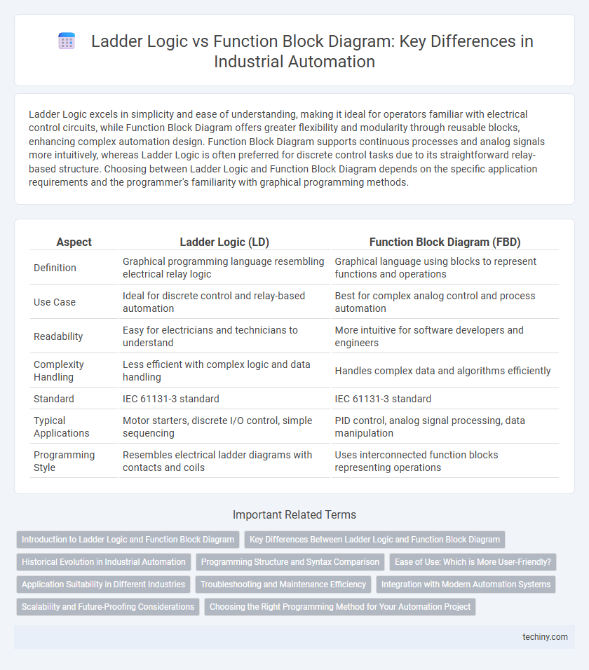
Ladder Logic excels in simplicity and ease of understanding, making it ideal for operators familiar with electrical control circuits, while Function Block Diagram offers greater flexibility and modularity through reusable blocks, enhancing complex automation design. Function Block Diagram supports continuous processes and analog signals more intuitively, whereas Ladder Logic is often preferred for discrete control tasks due to its straightforward relay-based structure. Choosing between Ladder Logic and Function Block Diagram depends on the specific application requirements and the programmer's familiarity with graphical programming methods.
Table of Comparison
| Aspect | Ladder Logic (LD) | Function Block Diagram (FBD) |
|---|---|---|
| Definition | Graphical programming language resembling electrical relay logic | Graphical language using blocks to represent functions and operations |
| Use Case | Ideal for discrete control and relay-based automation | Best for complex analog control and process automation |
| Readability | Easy for electricians and technicians to understand | More intuitive for software developers and engineers |
| Complexity Handling | Less efficient with complex logic and data handling | Handles complex data and algorithms efficiently |
| Standard | IEC 61131-3 standard | IEC 61131-3 standard |
| Typical Applications | Motor starters, discrete I/O control, simple sequencing | PID control, analog signal processing, data manipulation |
| Programming Style | Resembles electrical ladder diagrams with contacts and coils | Uses interconnected function blocks representing operations |
Introduction to Ladder Logic and Function Block Diagram
Ladder Logic and Function Block Diagram are two widely used programming languages in industrial automation for programmable logic controllers (PLCs). Ladder Logic resembles electrical relay logic schematics, using graphical symbols that represent contacts and coils to facilitate straightforward logic design and troubleshooting. Function Block Diagram employs pre-defined functional blocks like timers and counters, enabling complex control processes through easy-to-understand graphical components and data flow connections.
Key Differences Between Ladder Logic and Function Block Diagram
Ladder Logic uses graphical symbols resembling electrical relay logic, primarily focusing on sequential control, while Function Block Diagram employs interconnected blocks representing functions for complex data processing and continuous control. Ladder Logic is widely used in discrete manufacturing processes due to its simplicity and ease of troubleshooting, whereas Function Block Diagram excels in applications requiring modular design and analog signal manipulation. The key differences also include Ladder Logic's event-driven execution versus the cyclic execution model of Function Block Diagram, impacting their suitability for different automation tasks.
Historical Evolution in Industrial Automation
Ladder Logic, originating in the 1960s, was designed to mimic electrical relay logic for easier adoption by electricians in industrial automation. Function Block Diagram (FBD) emerged later in the 1980s under IEC 61131-3 standards, providing a graphical programming approach that enhances modularity and reusability of control functions. Both languages reflect the evolution from hardware-centric control systems to software-driven, flexible automation solutions in manufacturing environments.
Programming Structure and Syntax Comparison
Ladder Logic uses a graphical programming structure resembling electrical relay logic with rungs and contacts, making it intuitive for electricians familiar with circuit diagrams. Function Block Diagram offers a modular approach with blocks representing functions interconnected by lines, enabling complex process control with reusable code components. Syntax in Ladder Logic is symbol-based and visually oriented, whereas Function Block Diagram syntax focuses on data flow between function blocks, enhancing clarity for process-based automation systems.
Ease of Use: Which is More User-Friendly?
Ladder Logic offers a visual representation resembling electrical relay circuits, making it intuitive for technicians familiar with traditional wiring diagrams, enhancing ease of use. Function Block Diagram (FBD) simplifies complex processes through modular blocks, promoting clarity and reusability, which benefits programmers with software backgrounds. User-friendliness depends on the user's expertise, with Ladder Logic favored by electricians and FBD preferred by engineers focused on process automation.
Application Suitability in Different Industries
Ladder Logic excels in discrete manufacturing and automotive industries due to its straightforward representation of relay logic, facilitating easy troubleshooting and control of sequential processes. Function Block Diagram (FBD) is preferred in process industries such as chemical, oil and gas, and water treatment, where complex continuous control and analog signal processing require modular and reusable function blocks. Choosing between Ladder Logic and FBD depends on the industry-specific demands for process complexity, ease of maintenance, and integration with existing control systems.
Troubleshooting and Maintenance Efficiency
Ladder Logic offers straightforward visual representation resembling electrical relay circuits, making it easier for technicians with electrical backgrounds to troubleshoot and maintain automation systems quickly. Function Block Diagram (FBD) organizes control functions into modular blocks, enhancing diagnostics through clear function boundaries and reusable code, which reduces maintenance time and errors. While Ladder Logic excels in simplicity for fault detection, FBD improves efficiency by simplifying complex process visualization and enabling faster updates during system modifications.
Integration with Modern Automation Systems
Ladder Logic offers seamless integration with programmable logic controllers (PLCs) commonly used in industrial automation, enabling efficient control of discrete manufacturing processes. Function Block Diagram (FBD) enhances integration by providing modular, reusable blocks that simplify complex tasks and facilitate communication with advanced automation systems such as SCADA and DCS. Both approaches support interoperability with Industry 4.0 technologies, but FBD's graphical nature and scalability often provide superior adaptability for integrating IoT devices and real-time data analytics.
Scalability and Future-Proofing Considerations
Ladder Logic offers simplicity and ease of troubleshooting, making it ideal for small to medium-scale automation projects but may face challenges in scalability as system complexity grows. Function Block Diagram (FBD) supports modular design and reusable code, enhancing scalability and future-proofing by facilitating easier upgrades and integration with advanced automation technologies. Industrial automation systems leveraging FBD benefit from improved maintainability and adaptability to evolving process requirements compared to traditional Ladder Logic implementations.
Choosing the Right Programming Method for Your Automation Project
Selecting the appropriate programming method for automation projects depends on system complexity and operator familiarity; Ladder Logic offers simplicity and ease of troubleshooting for relay-based control, making it ideal for straightforward applications. Function Block Diagram excels in handling complex processes and modular design, allowing reusability and graphical representation of functions, which improves scalability and maintenance. Evaluating project requirements, including real-time performance and debugging needs, ensures the optimal choice between Ladder Logic and Function Block Diagram programming languages.
Ladder Logic vs Function Block Diagram Infographic