Fan-out and fan-in are critical concepts in hardware engineering that describe the relationships between components in a digital circuit. Fan-out refers to the number of gate inputs a single output can drive without degrading performance, influencing signal integrity and timing. Fan-in denotes the number of inputs a gate can accept, affecting the gate's complexity and propagation delay in signal processing.
Table of Comparison
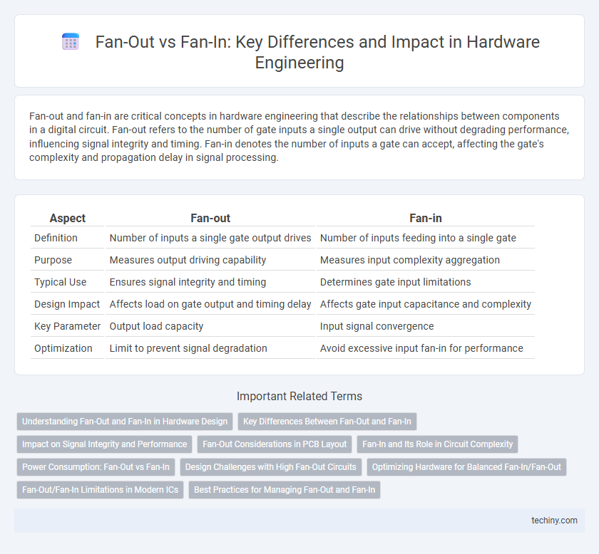
| Aspect | Fan-out | Fan-in |
|---|---|---|
| Definition | Number of inputs a single gate output drives | Number of inputs feeding into a single gate |
| Purpose | Measures output driving capability | Measures input complexity aggregation |
| Typical Use | Ensures signal integrity and timing | Determines gate input limitations |
| Design Impact | Affects load on gate output and timing delay | Affects gate input capacitance and complexity |
| Key Parameter | Output load capacity | Input signal convergence |
| Optimization | Limit to prevent signal degradation | Avoid excessive input fan-in for performance |
Understanding Fan-Out and Fan-In in Hardware Design
Fan-out in hardware design refers to the number of gate inputs driven by the output of a single gate, impacting signal strength and propagation delay. Fan-in denotes the number of inputs a logic gate can handle, influencing circuit complexity and response time. Managing optimal fan-out and fan-in ratios is critical for ensuring reliable performance, minimizing power consumption, and maintaining signal integrity in digital circuits.
Key Differences Between Fan-Out and Fan-In
Fan-out refers to the number of logic gates or circuits an output can drive, directly impacting signal integrity and speed in hardware engineering. Fan-in denotes the number of inputs a gate or circuit can handle, influencing complexity and delay in logic operations. Key differences include fan-out determining output drive capability, while fan-in constraints affect input loading and gate functionality.
Impact on Signal Integrity and Performance
Fan-out significantly affects signal integrity by increasing load capacitance on the driving gate, which can degrade signal rise and fall times, leading to slower circuit performance. High fan-in gates contribute to greater input capacitance, increasing delay and reducing switching speed, thereby impacting overall system timing and efficiency. Optimizing fan-out and fan-in levels is crucial for maintaining signal integrity and maximizing hardware performance in complex integrated circuits.
Fan-Out Considerations in PCB Layout
Fan-out considerations in PCB layout center on optimizing signal integrity and minimizing crosstalk by carefully planning trace routing and component placement. Adequate spacing and controlled impedance ensure reliable connections when signals fan out from a single source to multiple destinations. Proper fan-out design reduces electromagnetic interference and enhances overall circuit performance in complex hardware engineering projects.
Fan-In and Its Role in Circuit Complexity
Fan-in refers to the number of input signals a logic gate can handle, critically influencing circuit complexity by determining how many signals converge at a single gate. Higher fan-in levels enable more compact and efficient designs but can lead to increased gate delay and power consumption due to greater capacitive loading. Optimizing fan-in balances performance and complexity, essential for scalable hardware engineering and integrated circuit design.
Power Consumption: Fan-Out vs Fan-In
Fan-out significantly impacts power consumption by increasing the capacitive load on the driving gate, leading to higher dynamic power dissipation due to more gate inputs being driven simultaneously. Fan-in affects power consumption through increased input capacitance and device complexity within a gate, resulting in greater leakage currents and slower switching speeds. Optimizing fan-out and fan-in parameters is essential for minimizing power consumption in high-performance integrated circuit designs.
Design Challenges with High Fan-Out Circuits
High fan-out circuits impose significant design challenges due to increased capacitive loading, leading to slower signal propagation and higher power consumption. Managing signal integrity requires careful buffer insertion and optimized transistor sizing to balance drive strength and delay. Thermal management also becomes critical as high fan-out nodes can generate localized hot spots, impacting overall device reliability.
Optimizing Hardware for Balanced Fan-In/Fan-Out
Optimizing hardware for balanced fan-in and fan-out enhances signal integrity and reduces latency in digital circuits by ensuring each logic gate drives an appropriate number of inputs and receives a manageable number of signals. Proper balancing minimizes capacitive loading and power consumption, which is crucial for maintaining high performance and reliability in integrated circuit design. Techniques such as buffer insertion and logic restructuring are commonly employed to achieve an optimal fan-in/fan-out ratio, improving timing margins and overall system efficiency.
Fan-Out/Fan-In Limitations in Modern ICs
Fan-out and fan-in limitations in modern integrated circuits (ICs) significantly impact signal integrity and circuit performance. Excessive fan-out increases load capacitance on a driving gate, leading to slower signal transitions and higher power dissipation, while high fan-in complicates input transistor configurations, causing increased delay and reduced switching speed. Advanced semiconductor technologies often require careful balancing of fan-out and fan-in to optimize timing, minimize crosstalk, and ensure reliable operation in high-density IC designs.
Best Practices for Managing Fan-Out and Fan-In
Effective management of fan-out and fan-in in hardware engineering requires minimizing excessive fan-out to reduce signal degradation and timing delays, typically maintaining fan-out below recommended limits such as 10 to 20 loads per output. Incorporating buffer stages and using standardized cell libraries with optimized drive strengths can improve signal integrity and timing closure when fan-out is unavoidable. For fan-in, best practices involve limiting the number of inputs to logic gates to prevent increased propagation delays and noise susceptibility, often by employing hierarchical design and partitioning techniques.
Fan-out vs Fan-in Infographic