In-circuit testing (ICT) offers detailed fault detection by physically probing individual components on a circuit board, ensuring connectivity and functionality through direct electrical measurements. Boundary scan leverages the IEEE 1149.1 standard to test interconnections and internal nodes without physical probes, enabling access to hard-to-reach areas and reducing the need for test fixtures. Both methods complement each other by combining ICT's precision with boundary scan's efficiency in diagnosing complex printed circuit board assemblies.
Table of Comparison
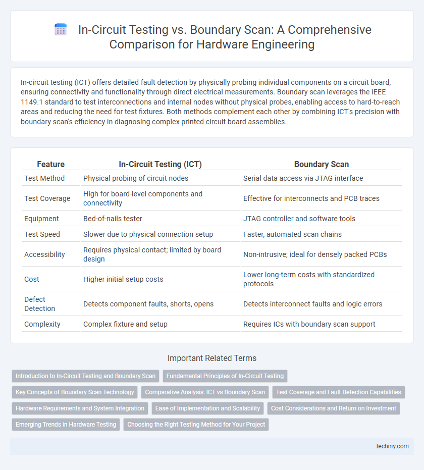
| Feature | In-Circuit Testing (ICT) | Boundary Scan |
|---|---|---|
| Test Method | Physical probing of circuit nodes | Serial data access via JTAG interface |
| Test Coverage | High for board-level components and connectivity | Effective for interconnects and PCB traces |
| Equipment | Bed-of-nails tester | JTAG controller and software tools |
| Test Speed | Slower due to physical connection setup | Faster, automated scan chains |
| Accessibility | Requires physical contact; limited by board design | Non-intrusive; ideal for densely packed PCBs |
| Cost | Higher initial setup costs | Lower long-term costs with standardized protocols |
| Defect Detection | Detects component faults, shorts, opens | Detects interconnect faults and logic errors |
| Complexity | Complex fixture and setup | Requires ICs with boundary scan support |
Introduction to In-Circuit Testing and Boundary Scan
In-circuit testing (ICT) involves applying electrical probes directly to the pins of a populated printed circuit board (PCB) to verify component placement, solder joint integrity, and functionality. Boundary scan, based on the IEEE 1149.1 standard, uses built-in test logic in integrated circuits to enable testing of interconnections and internal nodes without physical access to circuit pins. ICT excels at detecting manufacturing defects on assembled PCBs, while boundary scan offers enhanced test coverage for complex digital circuits and facilitates debugging through serial data chains.
Fundamental Principles of In-Circuit Testing
In-circuit testing relies on physical access to individual pins of integrated circuits through test probes, allowing measurement of electrical characteristics such as resistance, capacitance, and signal integrity directly on the assembled PCB. This method verifies component placement, solder joints, and detects manufacturing defects by applying test vectors and analyzing response patterns. Boundary scan, in contrast, uses the IEEE 1149.1 standard to test interconnections between ICs via a serial shift register architecture, enabling internal node observation without direct physical probing.
Key Concepts of Boundary Scan Technology
Boundary scan technology enables the testing of interconnects on printed circuit boards (PCBs) without physical test probes, using a standardized IEEE 1149.1 protocol. It incorporates a shift register architecture within integrated circuits that allows for serial data input/output and isolation of individual pins for fault detection and diagnosis. This method enhances testing efficiency, reduces manufacturing costs, and supports complex board designs where traditional in-circuit testing is challenging.
Comparative Analysis: ICT vs Boundary Scan
In-circuit testing (ICT) excels at detecting manufacturing defects such as open circuits, shorts, and component failures by directly probing test points on the PCB, offering high fault coverage for assembled boards. Boundary scan technology, standardized under IEEE 1149.1, enables testing of interconnects and internal logic through a serial chain of test cells, facilitating non-intrusive testing without physical test probes and improving access to densely packed or complex PCBs. While ICT provides detailed component-level diagnostics requiring physical access, boundary scan offers scalable testing for complex systems and enhanced fault isolation in scenarios where traditional probing is limited or impractical.
Test Coverage and Fault Detection Capabilities
In-circuit testing (ICT) offers high fault detection capabilities for assembled printed circuit boards by directly accessing physical pins to identify shorts, opens, and component failures. Boundary scan testing enhances test coverage for complex, high-density PCBs by enabling fault detection in interconnects and integrated circuits where physical probe access is limited. Combining ICT and boundary scan maximizes test coverage and fault detection accuracy by leveraging direct hardware probing alongside internal scan chain diagnostics.
Hardware Requirements and System Integration
In-circuit testing (ICT) requires physical access to test points on the PCB and specialized fixtures, making it highly dependent on hardware design for probe placement and accessibility. Boundary scan leverages JTAG protocols to test interconnects and components without physical probes, reducing the need for dedicated test pads and fixtures, which simplifies system integration. Hardware requirements for boundary scan favor designs with compliant TAP controllers, enabling seamless integration into automated test systems and in-system programming workflows.
Ease of Implementation and Scalability
In-circuit testing offers straightforward implementation for simple and moderate complexity boards, leveraging direct physical access to test points but faces scalability challenges as pin counts and component density increase. Boundary scan excels in scalability, enabling efficient testing and diagnostics of complex multi-layer PCBs with high pin densities through serial communication protocols without requiring physical test probes. This method reduces setup time and simplifies automation, making it more suitable for modern high-volume manufacturing environments.
Cost Considerations and Return on Investment
In-circuit testing (ICT) typically incurs higher initial setup costs due to the need for physical test fixtures and probes, whereas boundary scan technology reduces hardware expenses by enabling testing through the device's built-in scan chains. Boundary scan offers superior scalability and lower maintenance costs, improving return on investment (ROI) for complex, high-volume PCB assemblies by minimizing downtime and rework. ICT may deliver faster fault diagnosis for simpler boards but often results in increased labor and fixture costs that can diminish long-term ROI compared to boundary scan solutions.
Emerging Trends in Hardware Testing
Emerging trends in hardware testing emphasize the integration of in-circuit testing (ICT) with boundary scan techniques to enhance fault coverage and diagnostic accuracy. Advances in automated test equipment (ATE) enable faster identification of manufacturing defects and improve testability for complex multi-layer PCBs. The convergence of ICT and boundary scan supports increased test automation and real-time monitoring, reducing test cycle times and manufacturing costs.
Choosing the Right Testing Method for Your Project
In-circuit testing (ICT) offers comprehensive fault detection at the component level, making it ideal for projects with densely packed PCBs and high accessibility to test points. Boundary scan excels in testing complex integrated circuits and inaccessible solder joints, suitable for modern designs with limited physical access and high pin counts. Selecting the right method depends on factors like PCB complexity, test coverage requirements, production volume, and cost constraints to ensure efficient fault isolation and reduced test cycle time.
In-circuit testing vs Boundary scan Infographic