Isolated ground and chassis ground serve distinct purposes in hardware engineering to reduce electromagnetic interference and enhance signal integrity. Isolated ground provides a dedicated return path separated from the chassis, minimizing noise coupling in sensitive circuits, whereas chassis ground connects directly to the equipment's metal enclosure, serving primarily as a safety reference and common grounding point. Proper implementation of isolated ground can improve performance in audio, medical, and precision measurement systems by preventing ground loops and interference.
Table of Comparison
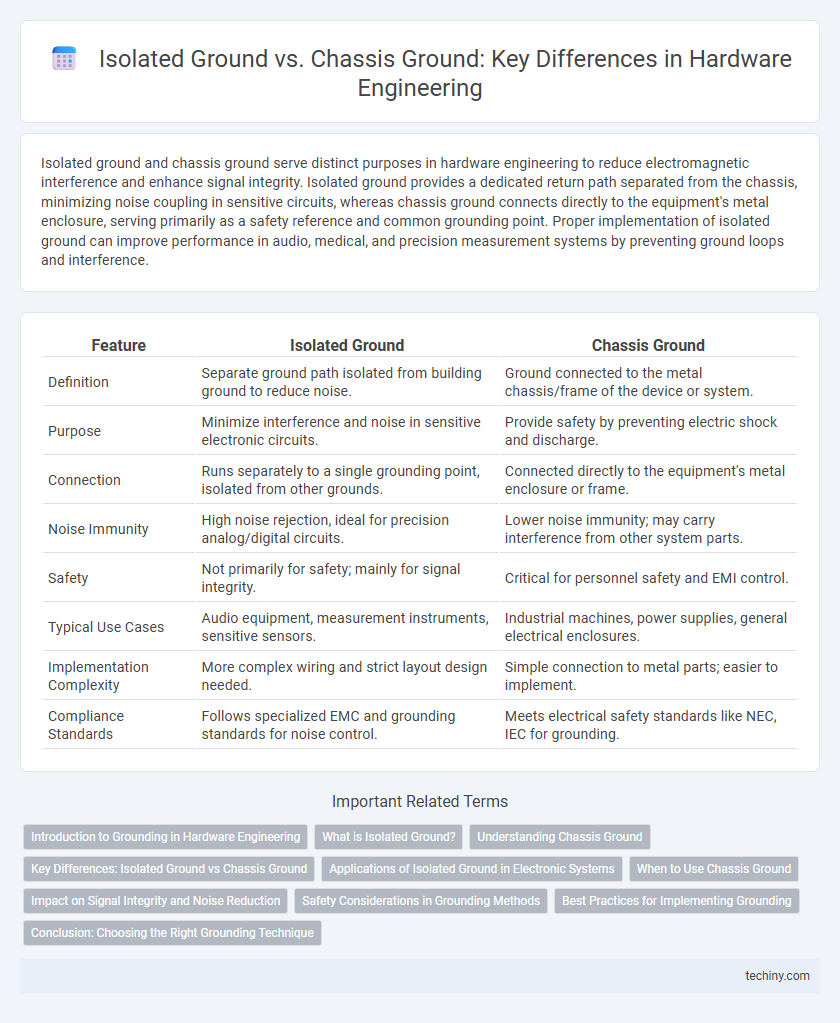
| Feature | Isolated Ground | Chassis Ground |
|---|---|---|
| Definition | Separate ground path isolated from building ground to reduce noise. | Ground connected to the metal chassis/frame of the device or system. |
| Purpose | Minimize interference and noise in sensitive electronic circuits. | Provide safety by preventing electric shock and discharge. |
| Connection | Runs separately to a single grounding point, isolated from other grounds. | Connected directly to the equipment's metal enclosure or frame. |
| Noise Immunity | High noise rejection, ideal for precision analog/digital circuits. | Lower noise immunity; may carry interference from other system parts. |
| Safety | Not primarily for safety; mainly for signal integrity. | Critical for personnel safety and EMI control. |
| Typical Use Cases | Audio equipment, measurement instruments, sensitive sensors. | Industrial machines, power supplies, general electrical enclosures. |
| Implementation Complexity | More complex wiring and strict layout design needed. | Simple connection to metal parts; easier to implement. |
| Compliance Standards | Follows specialized EMC and grounding standards for noise control. | Meets electrical safety standards like NEC, IEC for grounding. |
Introduction to Grounding in Hardware Engineering
Isolated ground and chassis ground serve distinct functions in hardware engineering to ensure proper electrical performance and safety. Isolated ground is designed to prevent electrical noise interference by separating the grounding path from the main chassis, commonly used in sensitive electronic equipment. Chassis ground connects the device's metal frame to earth ground, providing a safe path for fault currents and protecting against electrical shock hazards.
What is Isolated Ground?
Isolated ground refers to a grounding system where the ground conductor is electrically separated from the building's metal chassis or earth ground to minimize electrical noise and interference in sensitive equipment. It is commonly used in hardware engineering to improve signal integrity and reduce ground loop problems by providing a dedicated, noise-free return path. This method ensures enhanced protection for delicate electronic components in precision instruments and communication systems.
Understanding Chassis Ground
Chassis ground refers to the grounding method where the metal frame or enclosure of hardware acts as the common reference point for electrical circuits, improving safety by directing fault currents away from sensitive components. It helps reduce electromagnetic interference (EMI) by providing a low-impedance path to dissipate noise and stabilize signal integrity. Understanding chassis ground is essential for hardware engineers to design reliable grounding schemes that protect devices and ensure compliance with electrical standards.
Key Differences: Isolated Ground vs Chassis Ground
Isolated ground uses a dedicated grounding conductor separated from building ground to minimize electrical noise and interference in sensitive hardware systems. Chassis ground connects directly to the equipment's metal enclosure, providing a common reference point and safety path for fault currents. The primary difference lies in the isolated ground's ability to reduce ground loop noise, while chassis ground ensures equipment safety through direct metal-to-ground bonding.
Applications of Isolated Ground in Electronic Systems
Isolated ground systems are essential in sensitive electronic applications such as medical equipment, audio recording studios, and precision measurement instruments, where minimizing electrical noise and interference is critical. By separating the grounding path from the chassis ground, isolated grounds prevent ground loops and reduce electromagnetic interference (EMI), enhancing signal integrity and system reliability. These grounds are particularly important in environments with complex power distribution, as they maintain a clean reference point for electronic circuits without the noise typically introduced by chassis grounding.
When to Use Chassis Ground
Chassis ground is essential when minimizing electromagnetic interference (EMI) in hardware systems by providing a low-resistance path to dissipate noise and static electricity from the device enclosure. It is commonly used in metal cases, shielding sensitive components, and ensuring user safety by preventing electric shock through grounding exposed conductive surfaces. Employ chassis ground in environments where equipment interfaces with external devices or power sources requiring consistent reference potential for reliable signal integrity.
Impact on Signal Integrity and Noise Reduction
Isolated ground systems significantly improve signal integrity by preventing noise currents from flowing through sensitive circuit grounds, thereby reducing electromagnetic interference and ground loop effects. In contrast, chassis ground is primarily used for safety and shielding, offering a direct path to earth but potentially introducing noise into signal lines due to shared grounding paths. Effective hardware engineering designs leverage isolated grounds to minimize common-mode noise and ensure stable, low-noise signal transmission critical for high-precision electronic devices.
Safety Considerations in Grounding Methods
Isolated grounds reduce electrical noise by separating sensitive circuit grounds from the building's common electrical ground, enhancing signal integrity in hardware systems. Chassis grounds provide a direct connection to the equipment frame and earth ground, ensuring user safety by preventing electrical shock during fault conditions. Implementing proper grounding methods in hardware design is essential to protect personnel and maintain equipment reliability by minimizing interference and fault current risks.
Best Practices for Implementing Grounding
Isolated ground systems minimize electrical noise by separating sensitive equipment grounds from building chassis grounds, essential in hardware engineering applications requiring signal integrity. Best practices for implementing grounding include using dedicated isolated ground conductors routed separately from noisy power lines and ensuring a single-point grounding scheme to prevent ground loops. Proper bonding of isolated ground bars and regular inspection of ground resistance values below 1 ohm enhances system stability and reduces electromagnetic interference.
Conclusion: Choosing the Right Grounding Technique
Selecting the appropriate grounding technique depends on the specific hardware application and interference sensitivity. Isolated ground provides superior noise immunity by separating sensitive circuits from the main electrical ground, ideal for precision measurement systems. Chassis ground ensures safety and common reference but may introduce noise in sensitive electronics, making it suitable for general-purpose or high-current equipment.
Isolated ground vs Chassis ground Infographic