NPN transistors are widely used in hardware engineering due to their faster switching speeds and better electron mobility compared to PNP transistors, which rely on hole movement. NPN devices typically handle higher current and voltage levels, making them ideal for high-performance circuits and digital logic applications. PNP transistors excel in low-side switching and positive ground systems, offering complementary functionality in push-pull amplifier designs alongside NPN counterparts.
Table of Comparison
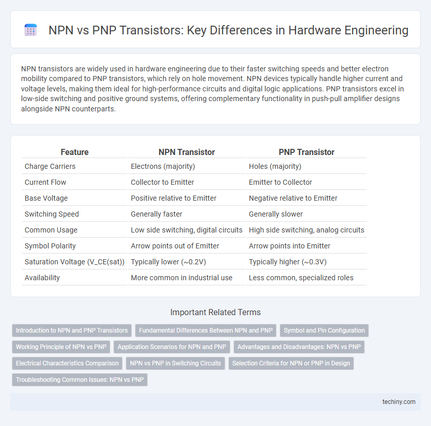
| Feature | NPN Transistor | PNP Transistor |
|---|---|---|
| Charge Carriers | Electrons (majority) | Holes (majority) |
| Current Flow | Collector to Emitter | Emitter to Collector |
| Base Voltage | Positive relative to Emitter | Negative relative to Emitter |
| Switching Speed | Generally faster | Generally slower |
| Common Usage | Low side switching, digital circuits | High side switching, analog circuits |
| Symbol Polarity | Arrow points out of Emitter | Arrow points into Emitter |
| Saturation Voltage (V_CE(sat)) | Typically lower (~0.2V) | Typically higher (~0.3V) |
| Availability | More common in industrial use | Less common, specialized roles |
Introduction to NPN and PNP Transistors
NPN and PNP transistors are fundamental types of bipolar junction transistors (BJTs) used extensively in hardware engineering for switching and amplification. An NPN transistor consists of a layer of P-type semiconductor sandwiched between two N-type layers, allowing current to flow when a positive voltage is applied to the base relative to the emitter. In contrast, a PNP transistor has a layer of N-type semiconductor between two P-type layers, conducting current when the base is at a lower potential than the emitter.
Fundamental Differences Between NPN and PNP
NPN and PNP transistors differ fundamentally in their charge carrier types and current flow directions; NPN transistors use electrons as majority carriers while PNP transistors use holes. In NPN transistors, current flows from the collector to the emitter when a positive voltage is applied to the base, whereas in PNP transistors, current flows from the emitter to the collector when the base is at a lower voltage than the emitter. The polarity of voltages required to turn the transistors on and their symbol representations also reflect these fundamental differences in semiconductor construction and operation.
Symbol and Pin Configuration
NPN and PNP transistors have distinct symbols and pin configurations critical for circuit design. The NPN symbol features an arrow on the emitter pointing outward, indicating current flow from the collector to the emitter, while the PNP symbol has the arrow pointing inward toward the base, showing current flow from the emitter to the collector. Pin configurations vary by manufacturer but commonly include the emitter, base, and collector arranged in either E-B-C or C-B-E order, requiring careful identification to ensure correct circuit integration.
Working Principle of NPN vs PNP
NPN transistors operate by allowing current to flow from the collector to the emitter when a positive voltage is applied to the base relative to the emitter, facilitating electron flow as the primary charge carriers. PNP transistors function by permitting current flow from the emitter to the collector when the base is at a lower potential than the emitter, with holes acting as the main charge carriers. The fundamental working principle difference lies in the direction of current flow and the type of charge carriers responsible for conduction in each transistor type.
Application Scenarios for NPN and PNP
NPN transistors are typically utilized in low-side switching applications where the load is connected to the positive supply, offering better electron mobility and faster switching speeds. PNP transistors are preferred in high-side switching scenarios, connecting the load to ground, enabling simpler control circuits in positive voltage environments. Selecting between NPN and PNP depends on circuit design requirements such as voltage polarity, current flow direction, and switching speed for optimal hardware performance.
Advantages and Disadvantages: NPN vs PNP
NPN transistors offer faster switching speeds and higher electron mobility, making them ideal for high-frequency and high-speed applications, while PNP transistors generally exhibit lower electron mobility, resulting in slower performance. The advantage of PNP transistors lies in their ability to source current efficiently in positive voltage circuits, which is beneficial for certain analog and power amplification designs. However, NPN transistors are typically preferred in digital circuits due to better current gain and simpler manufacturing processes, whereas PNP transistors might require more complex biasing configurations and can introduce greater power loss.
Electrical Characteristics Comparison
NPN transistors typically exhibit higher electron mobility, resulting in faster switching speeds and greater current gain (hFE) compared to PNP transistors. The voltage drop across the collector-emitter junction (VCE) in NPN devices is generally lower, enhancing efficiency in high-speed circuits. PNP transistors, on the other hand, often feature lower leakage current and better performance in negative voltage applications but usually have slower response times due to hole mobility characteristics.
NPN vs PNP in Switching Circuits
NPN transistors are preferred in switching circuits due to their ability to switch on when a positive voltage is applied to the base, allowing current to flow from the collector to the emitter. PNP transistors switch on with a negative base voltage relative to the emitter, causing current flow from emitter to collector, which can complicate circuit design in low-side switching applications. NPN devices generally offer faster switching speeds and more efficient current sinking, making them ideal for common ground reference circuits.
Selection Criteria for NPN or PNP in Design
NPN transistors are preferred in design for high-speed switching applications due to their electron mobility offering faster response times, while PNP transistors are often selected for low-side switching to source current in specific circuits. The choice between NPN and PNP depends on the required current direction, intended load positioning, and voltage level compatibility within the hardware architecture. Thermal stability, gain characteristics, and circuit topology also influence optimal transistor selection in hardware engineering.
Troubleshooting Common Issues: NPN vs PNP
Troubleshooting common issues in NPN vs PNP transistors often involves checking the polarity and biasing configurations, as NPN transistors require the emitter to be connected to ground while PNP transistors need the emitter connected to the positive voltage supply. Incorrect biasing can result in no current flow or transistor saturation, which is a frequent issue in circuit malfunctions. Verifying the correct orientation of the base-emitter junction and ensuring proper signal polarity improves diagnostic accuracy in both NPN and PNP device applications.
NPN vs PNP Infographic