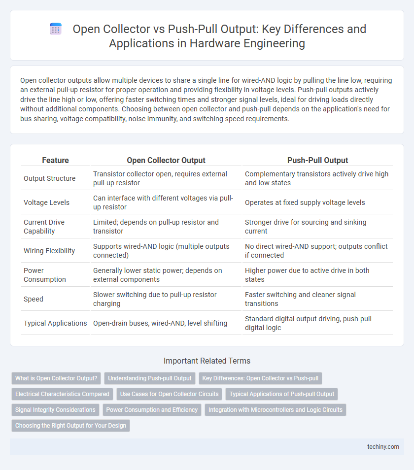
Open collector outputs allow multiple devices to share a single line for wired-AND logic by pulling the line low, requiring an external pull-up resistor for proper operation and providing flexibility in voltage levels. Push-pull outputs actively drive the line high or low, offering faster switching times and stronger signal levels, ideal for driving loads directly without additional components. Choosing between open collector and push-pull depends on the application's need for bus sharing, voltage compatibility, noise immunity, and switching speed requirements.
Table of Comparison
| Feature | Open Collector Output | Push-Pull Output |
|---|---|---|
| Output Structure | Transistor collector open, requires external pull-up resistor | Complementary transistors actively drive high and low states |
| Voltage Levels | Can interface with different voltages via pull-up resistor | Operates at fixed supply voltage levels |
| Current Drive Capability | Limited; depends on pull-up resistor and transistor | Stronger drive for sourcing and sinking current |
| Wiring Flexibility | Supports wired-AND logic (multiple outputs connected) | No direct wired-AND support; outputs conflict if connected |
| Power Consumption | Generally lower static power; depends on external components | Higher power due to active drive in both states |
| Speed | Slower switching due to pull-up resistor charging | Faster switching and cleaner signal transitions |
| Typical Applications | Open-drain buses, wired-AND, level shifting | Standard digital output driving, push-pull digital logic |
What is Open Collector Output?
Open collector output refers to a transistor configuration where the transistor's collector is left unconnected internally, requiring an external pull-up resistor to operate. This allows multiple open collector outputs to be wired together for wired-AND logic and enables level shifting between different voltage domains. Open collector outputs are commonly used in hardware engineering for interfacing between components with different voltage levels and for implementing simple communication protocols like I2C.
Understanding Push-pull Output
Push-pull output stage in hardware engineering employs two transistors that alternately pull the output voltage to the supply rail or ground, enabling faster switching and stronger signal drive compared to open collector configurations. This design minimizes signal distortion and power dissipation by providing both sourcing and sinking current capabilities, essential for driving low-impedance loads and achieving higher frequency performance. Push-pull outputs are widely used in integrated circuits requiring efficient, symmetrical drive strength and precise voltage level control in digital and analog applications.
Key Differences: Open Collector vs Push-pull
Open collector outputs allow multiple devices to share a single line by pulling it low, requiring an external pull-up resistor for proper signal levels, which enables wired-AND logic and simplifies interfacing with different voltage levels. Push-pull outputs actively drive the line both high and low, providing faster switching speeds and stronger drive capability but lack the open-collector's capability for line sharing and require careful voltage matching. The choice between open collector and push-pull output depends on application needs such as bus configuration, speed, power consumption, and voltage compatibility in hardware design.
Electrical Characteristics Compared
Open collector outputs allow multiple devices to share a common line for wired-AND functionality, operating by sinking current with an external pull-up resistor, resulting in slower rise times and lower power consumption. Push-pull outputs actively drive both high and low states using complementary transistors, enabling faster switching speeds and stronger drive capabilities at the cost of increased power dissipation. The choice between open collector and push-pull depends on required switching speed, current drive strength, and system architecture constraints in hardware design.
Use Cases for Open Collector Circuits
Open collector circuits are ideal for wired-AND logic applications, level shifting, and interfacing different voltage domains due to their open-drain transistor that requires an external pull-up resistor. These circuits excel in multi-point communication buses like I2C or interrupt lines where multiple outputs share a common line without causing damage from conflicting drive signals. Open collector outputs also facilitate driving higher voltage loads or isolating circuit elements, making them suitable for industrial control systems and LED driving.
Typical Applications of Push-pull Output
Push-pull output stages are commonly used in digital circuits requiring fast switching and low output impedance, such as microcontroller GPIOs, LED drivers, and audio amplifiers. This configuration enables efficient current sourcing and sinking, improving signal integrity in high-speed communication interfaces like SPI and I2C. Push-pull outputs are also preferred in power management and motor control applications due to their ability to actively drive both high and low levels.
Signal Integrity Considerations
Open collector outputs allow multiple devices to share a common line, minimizing signal conflicts but are prone to slower rise times and susceptibility to noise due to passive pull-up resistors. Push-pull outputs actively drive both high and low levels, providing faster switching speeds and improved signal integrity with clear voltage transitions. Careful selection between open collector and push-pull configurations impacts electromagnetic interference (EMI) and signal distortion in high-speed digital circuits.
Power Consumption and Efficiency
Open collector outputs consume less power in idle states due to the transistor only sinking current when active, making them efficient for low-frequency switching applications. Push-pull outputs provide faster switching speeds and better power efficiency at high frequencies by actively driving both high and low states, reducing power dissipation. Choosing between open collector and push-pull depends on the specific power consumption and efficiency requirements of the hardware design.
Integration with Microcontrollers and Logic Circuits
Open collector outputs require an external pull-up resistor to interface with microcontrollers or logic circuits, allowing multiple devices to share a single line for wired-AND logic, which is ideal for interrupt lines or bus arbitration. Push-pull outputs actively drive the line high or low, providing faster switching times and stronger drive capability suited for direct microcontroller I/O pins without extra components. Integration choice depends on the application's need for bus sharing, power consumption, and signal integrity in hardware engineering designs.
Choosing the Right Output for Your Design
Choosing the right output stage is critical for hardware engineers aiming to optimize circuit performance and power efficiency. Open collector outputs excel in wired-AND configurations and level shifting but require external pull-up resistors, which can slow signal edges. Push-pull outputs offer faster switching speeds and stronger drive capabilities, making them ideal for high-speed digital interfaces where signal integrity and power consumption are key design considerations.
Open Collector vs Push-pull Output Infographic