Step-down converters efficiently reduce higher input voltages to lower output voltages, making them ideal for powering low-voltage devices from high-voltage sources. Step-up converters, on the other hand, increase lower input voltages to higher output voltages, which is essential in applications requiring voltage boosting from batteries or renewable energy sources. Choosing between these converters depends on the specific voltage requirements and the power efficiency needed for hardware design.
Table of Comparison
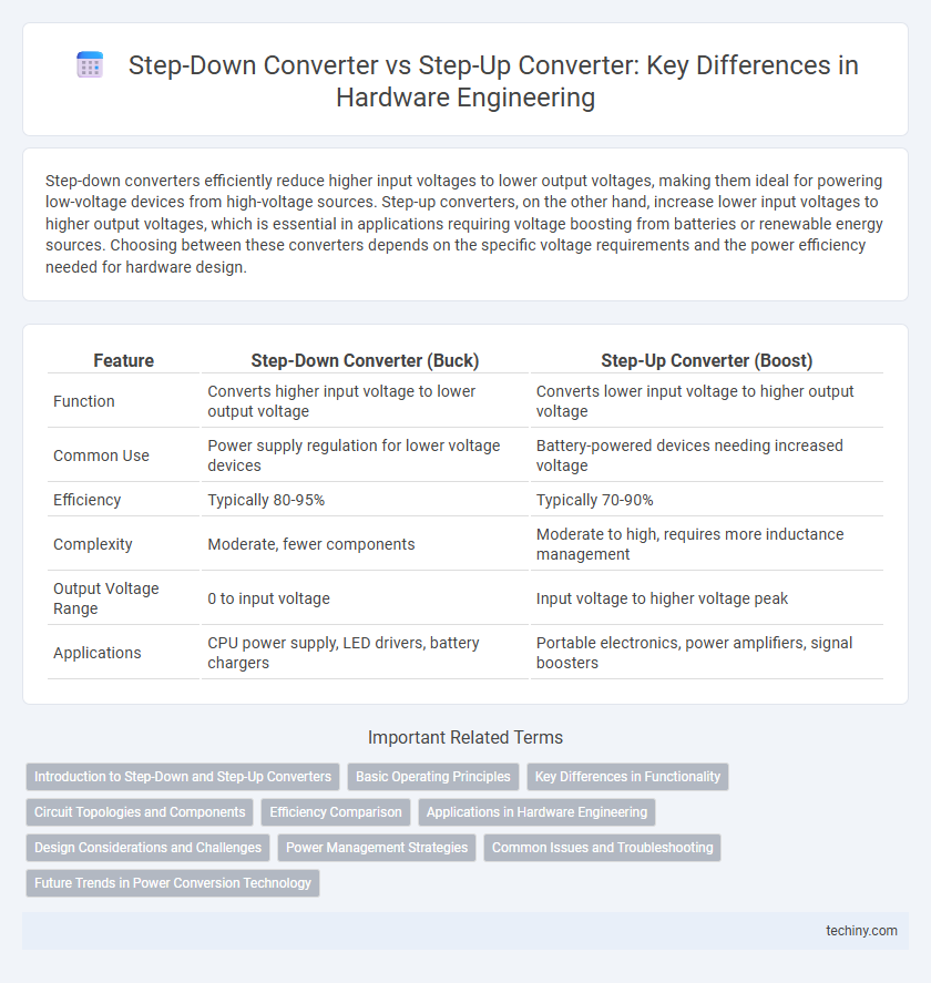
| Feature | Step-Down Converter (Buck) | Step-Up Converter (Boost) |
|---|---|---|
| Function | Converts higher input voltage to lower output voltage | Converts lower input voltage to higher output voltage |
| Common Use | Power supply regulation for lower voltage devices | Battery-powered devices needing increased voltage |
| Efficiency | Typically 80-95% | Typically 70-90% |
| Complexity | Moderate, fewer components | Moderate to high, requires more inductance management |
| Output Voltage Range | 0 to input voltage | Input voltage to higher voltage peak |
| Applications | CPU power supply, LED drivers, battery chargers | Portable electronics, power amplifiers, signal boosters |
Introduction to Step-Down and Step-Up Converters
Step-down converters, also known as buck converters, efficiently reduce higher input voltages to lower output voltages using a switching regulator to minimize power loss. Step-up converters, or boost converters, increase lower input voltages to higher output voltages by storing energy in an inductor and releasing it at a higher voltage level. Both converter types are essential in power management for optimizing voltage levels to match the requirements of electronic devices and circuits.
Basic Operating Principles
Step-down converters, also known as buck converters, reduce high input voltage to a lower output voltage by rapidly switching a transistor and storing energy in an inductor before releasing it at a reduced voltage level. Step-up converters, or boost converters, increase low input voltage to a higher output voltage by storing energy in the inductor during the transistor's conduction phase and releasing it when the transistor switches off. Both converters rely on pulse-width modulation and energy storage components to regulate output voltage efficiently.
Key Differences in Functionality
Step-down converters lower the input voltage to a desired, stable output voltage, optimizing power efficiency in applications requiring voltage reduction. Step-up converters increase the input voltage to a higher output level, essential for devices operating above the supply voltage. Both converters use different topologies and control mechanisms to regulate voltage, impacting the selection based on power requirements and circuit design constraints.
Circuit Topologies and Components
Step-down converters typically use buck topology with components such as MOSFETs, inductors, and capacitors arranged to reduce voltage efficiently. Step-up converters utilize boost topology, employing inductors, diodes, and switches to increase voltage from the input supply. Both converter types depend on switching elements and energy storage components but differ in circuit arrangements to achieve voltage regulation.
Efficiency Comparison
Step-down converters typically achieve efficiencies between 80% and 95%, benefiting from lower voltage stress and reduced power loss during voltage reduction. Step-up converters generally exhibit efficiencies ranging from 70% to 90%, influenced by inductor losses and switching transients during voltage boosting. Efficiency in both topologies largely depends on component quality, switching frequency, and load conditions, with step-down converters often favored for applications requiring high efficiency at lower output voltages.
Applications in Hardware Engineering
Step-down converters are widely used in hardware engineering to efficiently reduce higher input voltages to lower output voltages, powering microcontrollers, sensors, and low-voltage digital circuits. Step-up converters are essential for applications requiring increased voltage levels, such as driving OLED displays, powering sensor modules from single-cell batteries, or boosting voltage in energy harvesting systems. Both converters optimize power management in embedded systems, ensuring stable voltage supply for diverse electronic components and extending battery life.
Design Considerations and Challenges
Step-down converters require careful thermal management and efficient inductor selection to handle high input voltages while minimizing power loss and electromagnetic interference. Step-up converters face challenges in maintaining stable output voltage under varying load conditions and ensuring fast response to transient changes, demanding precise control loop design. Both converter types must balance efficiency, size, and component stress to optimize performance in hardware engineering applications.
Power Management Strategies
Step-down converters efficiently regulate voltage by reducing higher input voltages to lower output levels, minimizing power loss through synchronous rectification and high-frequency switching technology. Step-up converters increase voltage from lower input sources using boost topology, emphasizing energy storage components like inductors to maintain stable output under varying load conditions. Power management strategies prioritize converter selection based on load requirements, efficiency curves, thermal performance, and transient response to optimize overall system reliability and battery life in hardware engineering applications.
Common Issues and Troubleshooting
Step-down converters often face issues like output voltage drop under heavy load, thermal overheating, and instability due to improper feedback loop compensation, which can be troubleshooted by verifying load conditions, improving heat dissipation, and adjusting the feedback network. Step-up converters commonly encounter problems such as inductor saturation, input voltage ripple affecting output regulation, and excessive electromagnetic interference, resolved through selecting appropriate inductors, input/output filtering, and shielding techniques. Both converter types benefit from thorough PCB layout optimization and component quality checks to minimize noise and enhance overall reliability.
Future Trends in Power Conversion Technology
Step-down converters and step-up converters are evolving with advancements in wide bandgap semiconductors like GaN and SiC, which improve efficiency and switching speeds in power conversion applications. Future trends emphasize integration of digital control and adaptive algorithms to optimize performance dynamically while reducing power losses. Innovations in compact, high-frequency designs support emerging demands in electric vehicles, renewable energy systems, and portable electronics.
Step-down converter vs Step-up converter Infographic