Voltage dividers distribute input voltage across multiple resistors in series, enabling precise voltage scaling for various circuit components. Current dividers allocate input current through parallel resistors, allowing specific current levels to flow into different branches of a circuit. Understanding the distinct roles and calculations for voltage and current dividers is essential for designing efficient and accurate analog circuits.
Table of Comparison
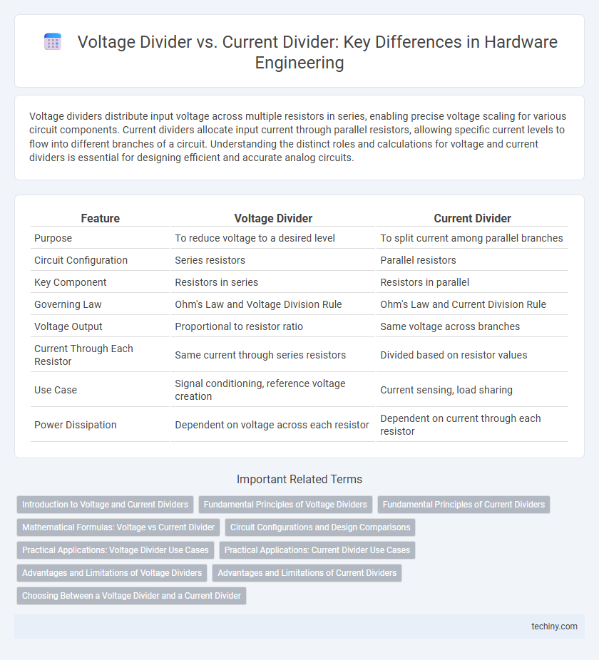
| Feature | Voltage Divider | Current Divider |
|---|---|---|
| Purpose | To reduce voltage to a desired level | To split current among parallel branches |
| Circuit Configuration | Series resistors | Parallel resistors |
| Key Component | Resistors in series | Resistors in parallel |
| Governing Law | Ohm's Law and Voltage Division Rule | Ohm's Law and Current Division Rule |
| Voltage Output | Proportional to resistor ratio | Same voltage across branches |
| Current Through Each Resistor | Same current through series resistors | Divided based on resistor values |
| Use Case | Signal conditioning, reference voltage creation | Current sensing, load sharing |
| Power Dissipation | Dependent on voltage across each resistor | Dependent on current through each resistor |
Introduction to Voltage and Current Dividers
Voltage dividers consist of resistors connected in series to produce a specific output voltage proportional to the input voltage, crucial for adjusting signal levels in hardware circuits. Current dividers, formed by parallel resistors, distribute input current into parts inversely proportional to resistor values, enabling precise current control in electrical systems. Both dividers are fundamental components in hardware engineering, supporting voltage regulation and current distribution across complex electronic devices.
Fundamental Principles of Voltage Dividers
Voltage dividers operate on the fundamental principle of dividing input voltage across series resistors proportionally to their resistance values, enabling precise voltage scaling within electronic circuits. The output voltage is a fraction of the total input voltage, calculated using the ratio of the resistor values, following Ohm's law and Kirchhoff's voltage law. This principle is essential for applications requiring reference voltages, signal attenuation, and biasing components in hardware engineering designs.
Fundamental Principles of Current Dividers
Current dividers operate based on the principle that the total current entering a parallel circuit divides inversely proportional to the resistance of each branch. Unlike voltage dividers, which split voltage across series resistors, current dividers allocate current through parallel resistors according to the formula I_n = I_total * (R_total / R_n). This fundamental concept ensures accurate current distribution in designing and analyzing complex electronic circuits.
Mathematical Formulas: Voltage vs Current Divider
Voltage dividers use the formula \( V_{out} = V_{in} \times \frac{R_2}{R_1 + R_2} \) to calculate the output voltage across resistor \( R_2 \) in a series circuit. Current dividers apply \( I_x = I_{total} \times \frac{R_{total}}{R_x} \) or more commonly \( I_x = I_{total} \times \frac{R_{other}}{R_1 + R_2} \) for parallel resistors, determining the current through a specific branch. These formulas enable precise control of voltage and current distributions in complex circuitry designs.
Circuit Configurations and Design Comparisons
Voltage dividers use series resistors to proportionally reduce voltage output based on resistance values, ideal for signal conditioning in circuits. Current dividers employ parallel resistors to distribute total current among branches according to conductance, optimizing current flow in multi-path circuits. Design comparisons highlight that voltage dividers prioritize voltage scaling with predictable output voltage, while current dividers focus on controlling branch currents, necessitating careful selection of resistor ratios to maintain desired circuit performance.
Practical Applications: Voltage Divider Use Cases
Voltage dividers are widely used in hardware engineering for sensor interfacing, enabling accurate voltage scaling from high-voltage signals to microcontroller-compatible inputs. They are essential in biasing transistors and setting reference voltages in analog circuits. Practical applications include adjusting signal levels in audio equipment, calibrating measurement devices, and providing input voltage control in power management systems.
Practical Applications: Current Divider Use Cases
Current dividers are extensively used in sensor circuits to precisely measure and allocate current across multiple components, enabling accurate data acquisition in hardware engineering. They play a crucial role in load balancing within parallel resistor networks, ensuring optimal current distribution for enhanced device performance. In power management systems, current dividers aid in protecting sensitive components by regulating current flow, preventing damage from overload conditions.
Advantages and Limitations of Voltage Dividers
Voltage dividers offer simplicity and ease of implementation for creating reference voltages or reducing voltage levels in circuits with minimal components. They are advantageous in low-current applications due to their passive design, but limitations arise with load sensitivity, as output voltage can vary significantly under changing load conditions. Precise voltage regulation and operation in high-current environments are less effective compared to active or current divider configurations.
Advantages and Limitations of Current Dividers
Current dividers efficiently split currents in parallel circuits, offering precise control over current distribution essential for sensor applications and load sharing. Their main advantage lies in simplicity and reliability for managing current without significantly affecting voltage levels. Limitations include sensitivity to component tolerances and potential issues with heat dissipation at high current levels, which can impact circuit stability and performance.
Choosing Between a Voltage Divider and a Current Divider
Choosing between a voltage divider and a current divider depends on the specific circuit requirements such as desired output type and load characteristics. Voltage dividers are preferred when stepping down voltage to feed sensitive components, offering predictable voltage outputs based on resistor ratios. Current dividers are ideal for distributing current among parallel branches, ensuring controlled current flow through each path by adjusting resistor values accordingly.
voltage divider vs current divider Infographic