UML (Unified Modeling Language) provides a comprehensive framework for visualizing, specifying, and documenting software systems, supporting various diagrams such as class, sequence, and use case diagrams to capture dynamic and static aspects. ERD (Entity-Relationship Diagram) specifically models data and database structures by illustrating entities, attributes, and relationships, making it ideal for designing relational databases. Choosing between UML and ERD depends on whether the focus is on overall software architecture and behavior (UML) or detailed data modeling and schema design (ERD).
Table of Comparison
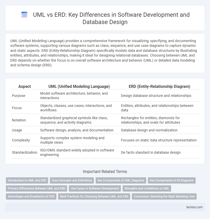
| Aspect | UML (Unified Modeling Language) | ERD (Entity-Relationship Diagram) |
|---|---|---|
| Purpose | Model software architecture, behavior, and interactions | Design database structure and relationships |
| Focus | Objects, classes, use cases, interactions, and workflows | Entities, attributes, and relationships between data |
| Notation | Standardized graphical symbols like class, sequence, and activity diagrams | Rectangles for entities, diamonds for relationships, and ovals for attributes |
| Usage | Software design, analysis, and documentation | Database design and normalization |
| Complexity | Supports complex system modeling and multiple views | Focuses on static data structure representation |
| Standardization | ISO/OMG standard widely adopted in software engineering | De facto standard in database design |
Introduction to UML and ERD
UML (Unified Modeling Language) is a standardized visual language in software development used to specify, visualize, construct, and document the artifacts of a system, focusing on behavior and structure through diagrams like class and sequence diagrams. ERD (Entity-Relationship Diagram) models data by illustrating entities, attributes, and relationships, primarily used for database design and data analysis. Both tools aid in system design, with UML providing a broader scope for software architecture and ERD concentrating on data schema representation.
Core Concepts and Definitions
UML (Unified Modeling Language) provides a comprehensive framework for visualizing, specifying, constructing, and documenting software systems through various diagrams such as class, sequence, and use case diagrams. ERD (Entity-Relationship Diagram) specializes in data modeling by illustrating the logical structure of databases, focusing on entities, attributes, and relationships. While UML captures both behavioral and structural aspects of software design, ERD is primarily concerned with the organization and interrelation of data within a database schema.
Key Components of UML Diagrams
UML diagrams encompass key components such as classes, objects, interfaces, and relationships including associations, generalizations, and dependencies, which collectively model the dynamic behavior and structure of software systems. These components enable detailed representation of workflows, interactions, and system architecture, facilitating clear communication among developers and stakeholders. In contrast, ERD primarily focuses on entities, attributes, and relationships for database schema design, lacking the behavioral and interactional detail found in UML diagrams.
Key Components of ER Diagrams
ER diagrams primarily focus on entities, attributes, and relationships, which represent data objects, their properties, and connections within a system. Entity sets define distinct objects, attributes describe characteristics of these entities, and relationship sets illustrate associations between entities. Key components such as primary keys uniquely identify entity instances, while cardinality constraints specify the numerical relationships between entities, providing a detailed data structure model.
Primary Differences Between UML and ERD
UML (Unified Modeling Language) is a versatile modeling language used to visualize, specify, construct, and document software systems, including class, sequence, and activity diagrams, while ERD (Entity-Relationship Diagram) specifically models the data structure and relationships within a database. UML covers a broader range of software design aspects such as behavior and interactions, whereas ERD focuses solely on the data entities and their interconnections. The primary difference lies in UML's capability for comprehensive software architecture representation compared to ERD's specialization in database schema design.
Use Cases in Software Development
Use Cases in software development provide a detailed description of system interactions from an end-user perspective, making UML diagrams particularly effective for modeling functional requirements. Unlike ERDs, which focus on the data structure and relationships within a database, UML Use Case diagrams emphasize dynamic system behavior and user goals. Leveraging UML Use Cases enhances requirements analysis, facilitates communication among stakeholders, and guides the design of software functionalities.
Strengths and Limitations of UML
UML excels in modeling dynamic system behaviors through use case, sequence, and activity diagrams, offering a comprehensive view of software architecture beyond static data structures. Its strength lies in enabling object-oriented design, facilitating communication among stakeholders, and supporting complex system interactions. However, UML can be overly detailed for straightforward data-centric applications where ERDs provide a clearer, more concise representation of relational database schemas.
Advantages and Drawbacks of ERD
Entity-Relationship Diagrams (ERDs) excel in visualizing database structure, emphasizing entities, relationships, and attributes, which facilitates clear data modeling and ensures accurate database design. However, ERDs focus primarily on data relationships and lack the capability to represent dynamic system behaviors, making them less suitable for modeling complex application logic compared to UML diagrams. Their simplicity can lead to limitations in capturing detailed interactions or system workflows necessary for comprehensive software development documentation.
Best Practices for Choosing Between UML and ERD
UML diagrams offer comprehensive modeling capabilities for software architecture, capturing dynamic behaviors and interactions, while ERD focuses on data structure and relationships, making it ideal for database design. Best practices recommend selecting UML when detailing system processes, class hierarchies, and use cases, whereas ERD is preferred for visualizing entity relationships and data normalization. Aligning the choice with project goals ensures clarity in communication and effective documentation throughout the software development lifecycle.
Conclusion: Selecting the Right Modeling Tool
Selecting the right modeling tool between UML and ERD depends on the project's scope and requirements, with UML offering comprehensive support for dynamic behavior and system architecture, while ERD focuses specifically on data structure and database design. UML diagrams such as class, sequence, and activity diagrams facilitate detailed visualization of software processes and interactions, enhancing object-oriented development. ERDs, by contrast, provide a clear blueprint for relational database schema, making them indispensable for data-centric applications.
UML vs ERD Infographic