Buck converters step down voltage efficiently by switching components that reduce input voltage to a lower, stable output ideal for low-voltage applications. Boost converters increase voltage levels by storing energy in an inductor and releasing it at a higher voltage, suitable for devices requiring a higher supply than the input source. Selecting between buck and boost converters depends on the specific power requirements and voltage regulation needs of the hardware system.
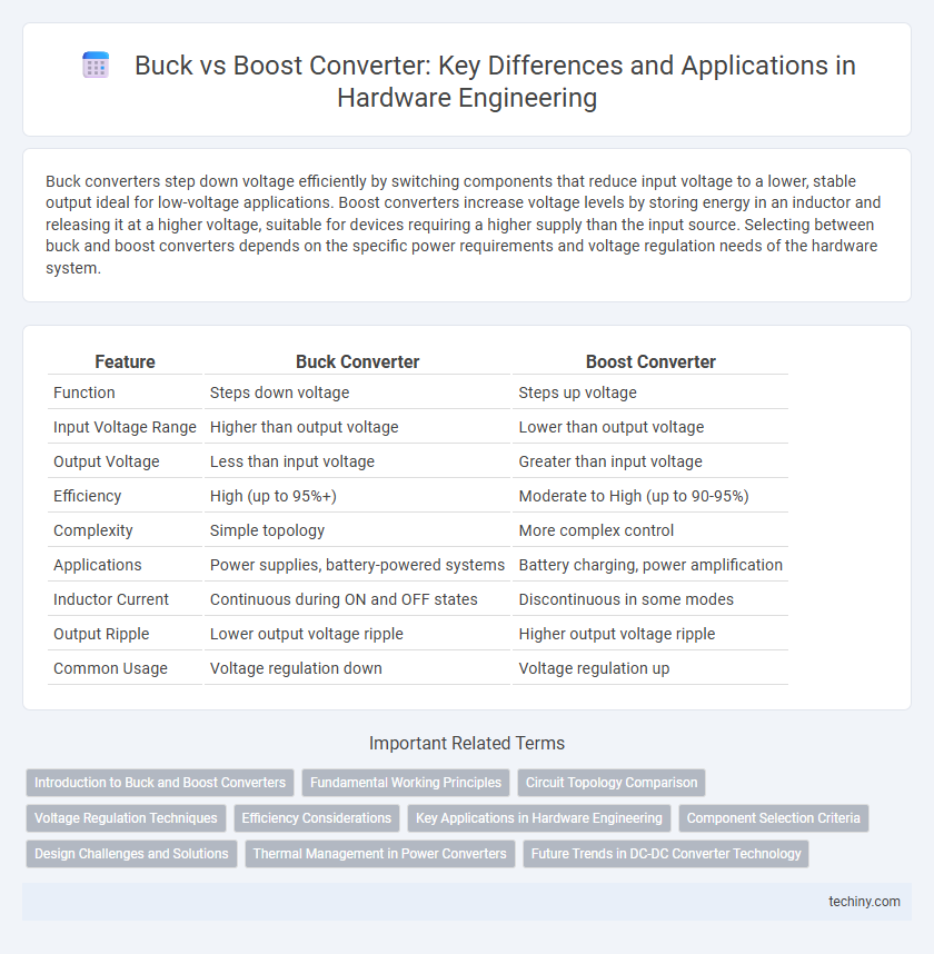
Table of Comparison
| Feature | Buck Converter | Boost Converter |
|---|---|---|
| Function | Steps down voltage | Steps up voltage |
| Input Voltage Range | Higher than output voltage | Lower than output voltage |
| Output Voltage | Less than input voltage | Greater than input voltage |
| Efficiency | High (up to 95%+) | Moderate to High (up to 90-95%) |
| Complexity | Simple topology | More complex control |
| Applications | Power supplies, battery-powered systems | Battery charging, power amplification |
| Inductor Current | Continuous during ON and OFF states | Discontinuous in some modes |
| Output Ripple | Lower output voltage ripple | Higher output voltage ripple |
| Common Usage | Voltage regulation down | Voltage regulation up |
Introduction to Buck and Boost Converters
Buck converters efficiently step down voltage levels by switching elements and inductors to regulate output voltage lower than the input. Boost converters raise voltage levels using similar switch-mode power supply principles but configure components to increase output voltage above the input. Both converters are essential in power management systems for optimizing energy usage in hardware engineering applications.
Fundamental Working Principles
Buck converters step down voltage by switching a transistor to connect and disconnect the input power source, storing energy in an inductor and releasing it at a lower voltage to the load. Boost converters increase voltage by switching the transistor to store energy in an inductor and then releasing it to the output at a higher voltage than the input. Both converters rely on pulse-width modulation (PWM) to control the switch timing, enabling efficient voltage regulation through energy transfer between input, inductor, and output.
Circuit Topology Comparison
Buck converters utilize a step-down circuit topology with a switch, inductor, diode, and output capacitor arranged to reduce voltage efficiently. Boost converters feature a step-up topology where the inductor stores energy during the switch-on phase and releases it to increase voltage above the input level using a diode and capacitor. The Buck converter's topology prioritizes lower output voltage with high efficiency, whereas the Boost converter's arrangement focuses on voltage amplification while maintaining energy transfer through its switching elements.
Voltage Regulation Techniques
Buck converters regulate voltage by stepping down the input voltage using pulse-width modulation (PWM) to control the duty cycle, thereby delivering a stable lower output voltage with high efficiency. Boost converters increase the voltage by storing energy in an inductor and releasing it at a higher voltage, employing voltage feedback loops and PWM to maintain precise output voltage regulation under varying load conditions. Both converters use closed-loop control systems with error amplifiers and compensation networks to dynamically adjust switching elements, ensuring consistent voltage output.
Efficiency Considerations
Buck converters typically exhibit higher efficiency than boost converters due to lower power dissipation in the switching elements during voltage step-down operations. Boost converters often experience increased conduction losses and voltage stress on components, which can reduce their overall efficiency under high load conditions. Optimizing switching frequency, inductor quality, and component selection is crucial for maximizing efficiency in both converter types.
Key Applications in Hardware Engineering
Buck converters are essential in hardware engineering for voltage step-down applications, such as powering microcontrollers and digital circuits where efficient voltage regulation is critical. Boost converters are widely used to increase voltage levels in battery-powered devices and LED drivers, ensuring stable operation under varying load conditions. Both converter types play a vital role in designing power management systems for embedded devices and renewable energy applications.
Component Selection Criteria
Component selection criteria for Buck converters prioritize low on-resistance MOSFETs to minimize conduction losses and efficient inductors with high saturation current ratings for stable output voltage regulation. Boost converters require components that handle higher voltage stress, including MOSFETs with high breakdown voltage and inductors designed for continuous current mode to reduce ripple. Capacitor choice in both converters emphasizes low equivalent series resistance (ESR) to maintain voltage stability and improve transient response.
Design Challenges and Solutions
Design challenges in buck converters include managing inductor current ripple and minimizing switching losses, which can be addressed by optimizing inductor selection and employing synchronous rectification techniques. Boost converters face difficulties in achieving high voltage gain without sacrificing efficiency or stability, solved through multi-phase design strategies and advanced control algorithms such as peak current mode control. Both converter types require careful layout considerations to reduce electromagnetic interference and thermal management strategies to maintain reliability under varying load conditions.
Thermal Management in Power Converters
Buck converters typically generate less heat due to their step-down voltage design, enabling more efficient thermal management with smaller heat sinks and reduced cooling requirements. Boost converters operate at higher voltages and often experience increased switching losses, necessitating robust thermal dissipation strategies such as advanced heat sinks and active cooling systems. Optimizing PCB layout for effective heat spreading and selecting components with low thermal resistance are critical for maintaining reliable operation in both buck and boost power converters.
Future Trends in DC-DC Converter Technology
Future trends in DC-DC converter technology emphasize integrating adaptive control algorithms, improving efficiency beyond 95%, and enhancing compactness with GaN (Gallium Nitride) and SiC (Silicon Carbide) semiconductors. Buck converters continue evolving with digital control for better transient response, while boost converters target higher voltage gains with reduced electromagnetic interference. Emerging wide-bandgap materials and AI-driven modulation techniques promise significant improvements in power density, thermal management, and system reliability for hardware engineering applications.
Buck vs Boost converter Infographic