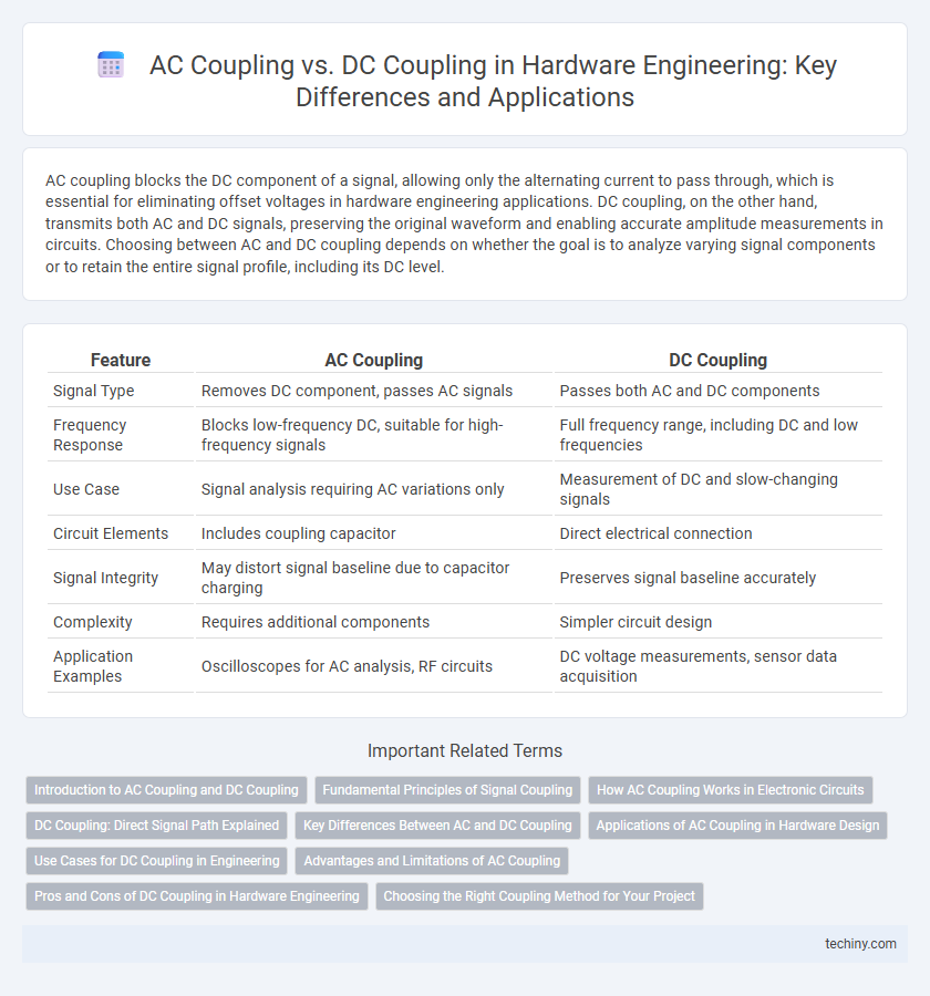
AC coupling blocks the DC component of a signal, allowing only the alternating current to pass through, which is essential for eliminating offset voltages in hardware engineering applications. DC coupling, on the other hand, transmits both AC and DC signals, preserving the original waveform and enabling accurate amplitude measurements in circuits. Choosing between AC and DC coupling depends on whether the goal is to analyze varying signal components or to retain the entire signal profile, including its DC level.
Table of Comparison
| Feature | AC Coupling | DC Coupling |
|---|---|---|
| Signal Type | Removes DC component, passes AC signals | Passes both AC and DC components |
| Frequency Response | Blocks low-frequency DC, suitable for high-frequency signals | Full frequency range, including DC and low frequencies |
| Use Case | Signal analysis requiring AC variations only | Measurement of DC and slow-changing signals |
| Circuit Elements | Includes coupling capacitor | Direct electrical connection |
| Signal Integrity | May distort signal baseline due to capacitor charging | Preserves signal baseline accurately |
| Complexity | Requires additional components | Simpler circuit design |
| Application Examples | Oscilloscopes for AC analysis, RF circuits | DC voltage measurements, sensor data acquisition |
Introduction to AC Coupling and DC Coupling
AC coupling uses a capacitor to block DC components, allowing only AC signals to pass, which is essential for removing DC offset in signal measurement and transmission. DC coupling offers a direct electrical connection, preserving both AC and DC components, enabling accurate measurement of low-frequency signals and DC levels. Selecting between AC and DC coupling depends on the specific application requirements, such as signal type, frequency range, and measurement precision in hardware engineering.
Fundamental Principles of Signal Coupling
AC coupling uses a capacitor to block DC components, allowing only the alternating current signal to pass, which helps eliminate offset voltage and low-frequency noise. DC coupling provides a direct electrical connection, preserving both AC and DC components of the signal for accurate representation of steady-state and transient behaviors. Choosing between AC and DC coupling depends on the need to retain baseline signal levels or isolate specific frequency components in hardware engineering applications.
How AC Coupling Works in Electronic Circuits
AC coupling in electronic circuits employs a capacitor to block direct current (DC) components while allowing alternating current (AC) signals to pass through, enabling the isolation of signal stages and preventing DC bias from affecting subsequent circuit elements. This technique is essential in signal conditioning to ensure only the desired AC waveform is transmitted, improving signal integrity in amplifiers and oscilloscopes. The capacitor's impedance decreases with increasing frequency, facilitating high-frequency signal transmission while suppressing low-frequency and DC components.
DC Coupling: Direct Signal Path Explained
DC coupling enables a direct signal path by transmitting both AC and DC components without distortion or filtering, preserving the original waveform integrity. This method is essential in applications requiring accurate low-frequency signal measurement, such as sensor interfacing and precision analog circuits. Unlike AC coupling, DC coupling maintains baseline signal levels, allowing real-time monitoring and control of steady-state voltage conditions.
Key Differences Between AC and DC Coupling
AC coupling uses a capacitor to block DC signals, allowing only AC signals to pass, which is ideal for measuring waveform variations without DC offset interference. DC coupling transmits both AC and DC components of a signal directly, preserving the original waveform including its DC level, essential for accurate voltage measurements. The choice between AC and DC coupling depends on whether the analysis requires eliminating DC offset (AC coupling) or capturing the complete signal including steady-state voltage (DC coupling).
Applications of AC Coupling in Hardware Design
AC coupling is widely used in hardware design for signal conditioning in communication systems, enabling the transmission of alternating signals without DC offset interference. It is essential for isolating different circuit sections, preventing DC bias from one stage affecting subsequent stages, particularly in high-frequency amplifier and data acquisition designs. Applications include sensor interfaces, audio equipment, and RF systems where accurate alternating signal representation is critical.
Use Cases for DC Coupling in Engineering
DC coupling is essential in hardware engineering for applications requiring accurate measurement of low-frequency or DC signals, such as power supply monitoring and sensor signal acquisition. It enables continuous signal transmission without distortion or loss of baseline information, which is critical for impedance analysis and feedback control systems. Engineers rely on DC coupling to maintain signal integrity in systems where the full frequency spectrum, including zero hertz, must be preserved for precise instrumentation and diagnostics.
Advantages and Limitations of AC Coupling
AC coupling effectively blocks DC components, allowing only AC signals to pass, which is ideal for isolating signal variations in data acquisition systems. This method reduces baseline drift and prevents DC offset errors, improving measurement accuracy in oscilloscopes and amplifiers. However, AC coupling introduces limitations such as low-frequency signal distortion and reduced response to slow or steady-state changes, making it unsuitable for applications requiring accurate DC level analysis.
Pros and Cons of DC Coupling in Hardware Engineering
DC coupling in hardware engineering enables accurate measurement of low-frequency and DC signals without distortion, making it ideal for precision analog circuits and sensor interfaces. However, it can introduce offset voltage errors and drift due to input bias currents and temperature variations, requiring careful calibration and compensation. Unlike AC coupling, DC coupling maintains the true signal baseline but demands higher input impedance and protection against potential DC voltage levels that might damage sensitive components.
Choosing the Right Coupling Method for Your Project
Selecting the appropriate coupling method depends on the signal characteristics and measurement goals in hardware engineering. AC coupling blocks DC components, ideal for observing small AC signals superimposed on large DC offsets, while DC coupling preserves both AC and DC signals, crucial for accurate analysis of low-frequency or static components. Consider the frequency range, signal amplitude, and potential offset impacts to ensure optimal signal integrity and measurement accuracy in your project.
AC coupling vs DC coupling Infographic