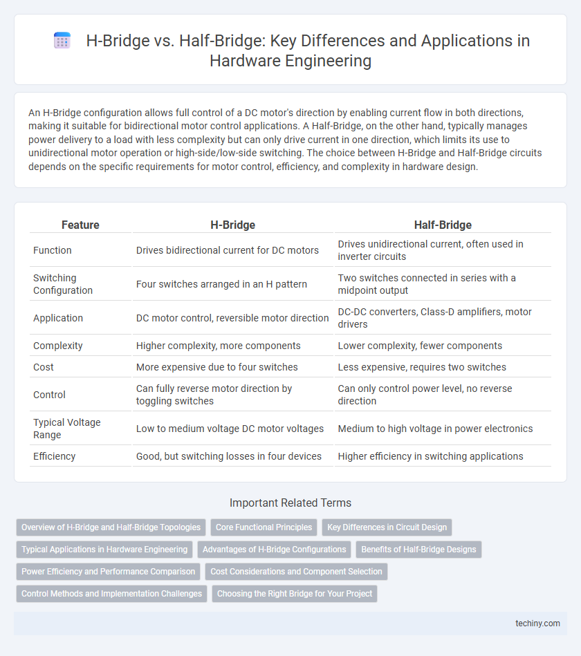
An H-Bridge configuration allows full control of a DC motor's direction by enabling current flow in both directions, making it suitable for bidirectional motor control applications. A Half-Bridge, on the other hand, typically manages power delivery to a load with less complexity but can only drive current in one direction, which limits its use to unidirectional motor operation or high-side/low-side switching. The choice between H-Bridge and Half-Bridge circuits depends on the specific requirements for motor control, efficiency, and complexity in hardware design.
Table of Comparison
| Feature | H-Bridge | Half-Bridge |
|---|---|---|
| Function | Drives bidirectional current for DC motors | Drives unidirectional current, often used in inverter circuits |
| Switching Configuration | Four switches arranged in an H pattern | Two switches connected in series with a midpoint output |
| Application | DC motor control, reversible motor direction | DC-DC converters, Class-D amplifiers, motor drivers |
| Complexity | Higher complexity, more components | Lower complexity, fewer components |
| Cost | More expensive due to four switches | Less expensive, requires two switches |
| Control | Can fully reverse motor direction by toggling switches | Can only control power level, no reverse direction |
| Typical Voltage Range | Low to medium voltage DC motor voltages | Medium to high voltage in power electronics |
| Efficiency | Good, but switching losses in four devices | Higher efficiency in switching applications |
Overview of H-Bridge and Half-Bridge Topologies
H-Bridge topology consists of four switching elements arranged in an H configuration to control the direction of current through a load, enabling bidirectional motor control and precise power delivery. Half-Bridge topology employs two switches and a midpoint capacitor to provide unidirectional current flow, commonly used in DC-DC converters and class-D amplifiers for efficient voltage regulation. Both topologies feature distinct switching arrangements that optimize power efficiency and control based on application requirements in hardware engineering.
Core Functional Principles
An H-Bridge circuit enables bidirectional control of a DC motor by using four switches arranged in an "H" configuration, allowing current to flow in both directions through the load. In contrast, a Half-Bridge consists of two switches and is typically used for unidirectional control or as a building block for more complex topologies, providing efficient switching between supply and ground. The core functional principle of the H-Bridge emphasizes full directional control, while the Half-Bridge optimizes simplicity and power management in switching applications.
Key Differences in Circuit Design
An H-Bridge circuit consists of four switching elements arranged in an "H" configuration, enabling bidirectional control of a load such as a DC motor, while a Half-Bridge uses only two switches connected in series, allowing unidirectional control with a midpoint output. The H-Bridge design supports full directional control and regenerative braking by enabling current flow in both directions, whereas the Half-Bridge primarily provides power to a load from a split supply, offering limited control complexity. Key differences include the number of transistors involved, complexity of gate drive circuitry, and the capability for load reversal, making H-Bridges more suitable for applications requiring precise motor control.
Typical Applications in Hardware Engineering
H-Bridge circuits are commonly used in motor control applications for bidirectional voltage control, enabling precise speed and direction management in robotics and automotive systems. Half-Bridge configurations are typically employed in power supply circuits, such as DC-DC converters and Class D audio amplifiers, where efficient switching and voltage regulation are critical. Both topologies optimize power delivery and switching performance but serve distinct roles depending on load requirements and control complexity.
Advantages of H-Bridge Configurations
H-Bridge configurations offer superior control of DC motors by enabling bidirectional current flow, allowing for both forward and reverse operation, which half-bridge circuits cannot inherently provide. This topology improves efficiency by minimizing voltage drops and ensures precise motor speed and torque control through PWM modulation. Enhanced fault tolerance and simplified braking mechanisms make H-Bridge designs ideal for advanced motor driver applications in hardware engineering.
Benefits of Half-Bridge Designs
Half-bridge designs offer improved efficiency and reduced component count compared to H-bridge configurations, making them ideal for applications requiring cost-effective power conversion. Their simpler topology minimizes switching losses and electromagnetic interference (EMI), enhancing overall system reliability in motor control and power regulation. Additionally, half-bridge circuits provide precise voltage control and faster switching speeds, which are critical in high-frequency DC-DC converters and motor drive applications.
Power Efficiency and Performance Comparison
H-Bridge circuits offer higher power efficiency in motor control applications by enabling bidirectional current flow and reducing power dissipation through synchronous switching techniques. In contrast, Half-Bridge configurations are simpler but typically exhibit lower efficiency due to increased voltage drops and limited current pathways. Performance-wise, H-Bridges provide superior torque control and smoother motor operation, making them ideal for demanding power electronics systems.
Cost Considerations and Component Selection
H-Bridge circuits typically incur higher costs due to their requirement for four switching devices and more complex control logic, making them suitable for bidirectional motor control in robotics and automotive applications. Half-Bridge designs use only two switching devices, leading to lower component costs and simplified layouts, ideal for unidirectional or simpler power applications. Selecting between H-Bridge and Half-Bridge hinges on evaluating the trade-off between system complexity, cost constraints, and the specific motor control requirements.
Control Methods and Implementation Challenges
H-Bridge control involves managing four switches in a configuration that enables full bidirectional current flow, providing precise motor direction and speed control but requiring complex timing algorithms to avoid shoot-through faults. Half-Bridge control uses two switches per leg, simplifying the driver circuitry but limiting the ability to reverse current, necessitating additional components for bidirectional control. Implementation challenges in H-Bridge circuits include managing switch dead-time and ensuring robust gate drive signals, whereas Half-Bridge designs face trade-offs in efficiency and require careful voltage balancing.
Choosing the Right Bridge for Your Project
Selecting between an H-Bridge and a half-bridge depends primarily on your application's power and control requirements. H-Bridge configurations enable full bidirectional control of DC motors, making them ideal for robotics and motor driver circuits requiring reversible operation. Half-Bridge circuits, often used in power conversion and audio amplification, offer simpler design and efficiency benefits when only unidirectional control or switching is necessary.
H-Bridge vs Half-Bridge Infographic