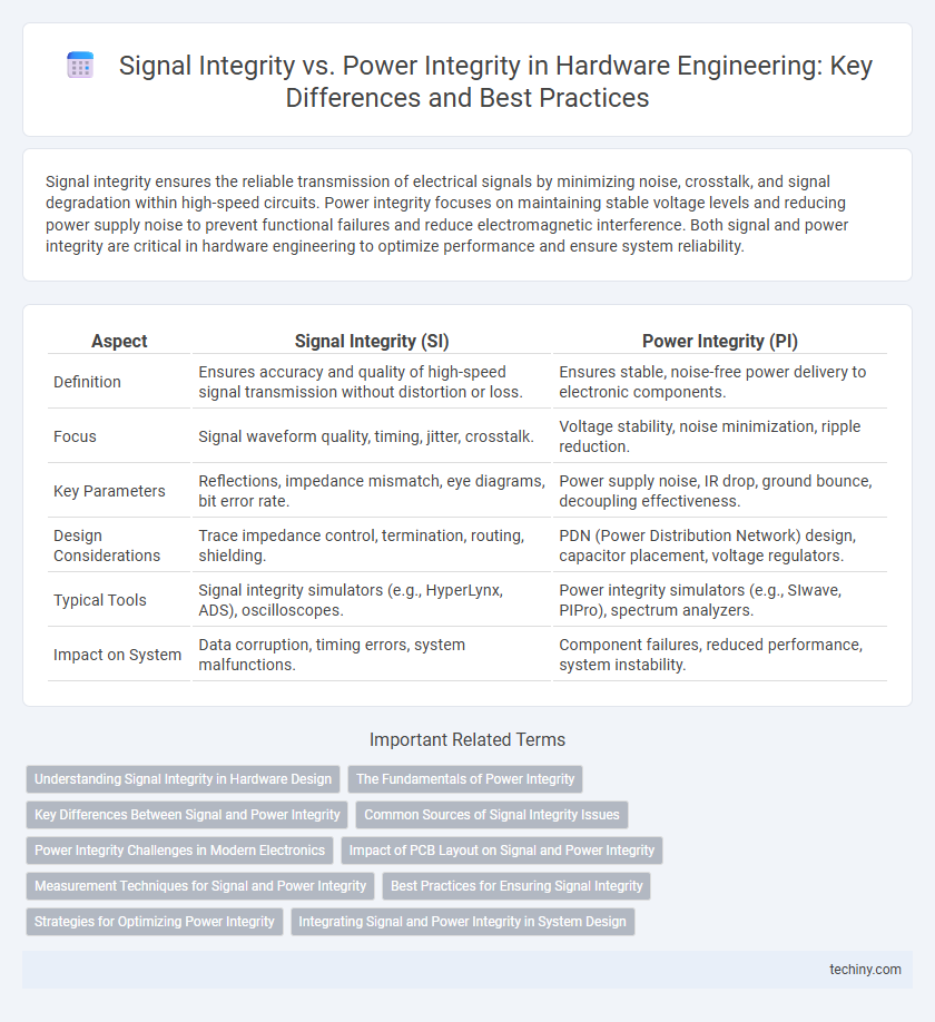
Signal integrity ensures the reliable transmission of electrical signals by minimizing noise, crosstalk, and signal degradation within high-speed circuits. Power integrity focuses on maintaining stable voltage levels and reducing power supply noise to prevent functional failures and reduce electromagnetic interference. Both signal and power integrity are critical in hardware engineering to optimize performance and ensure system reliability.
Table of Comparison
| Aspect | Signal Integrity (SI) | Power Integrity (PI) |
|---|---|---|
| Definition | Ensures accuracy and quality of high-speed signal transmission without distortion or loss. | Ensures stable, noise-free power delivery to electronic components. |
| Focus | Signal waveform quality, timing, jitter, crosstalk. | Voltage stability, noise minimization, ripple reduction. |
| Key Parameters | Reflections, impedance mismatch, eye diagrams, bit error rate. | Power supply noise, IR drop, ground bounce, decoupling effectiveness. |
| Design Considerations | Trace impedance control, termination, routing, shielding. | PDN (Power Distribution Network) design, capacitor placement, voltage regulators. |
| Typical Tools | Signal integrity simulators (e.g., HyperLynx, ADS), oscilloscopes. | Power integrity simulators (e.g., SIwave, PIPro), spectrum analyzers. |
| Impact on System | Data corruption, timing errors, system malfunctions. | Component failures, reduced performance, system instability. |
Understanding Signal Integrity in Hardware Design
Signal integrity in hardware design ensures that electrical signals maintain their intended shape and timing while traveling through circuit paths, preventing errors such as noise, crosstalk, and signal degradation. Key factors affecting signal integrity include impedance matching, proper termination, and controlled trace routing to minimize reflections and electromagnetic interference. Maintaining signal integrity is crucial for high-speed digital circuits to achieve reliable data transmission and optimal performance.
The Fundamentals of Power Integrity
Power integrity in hardware engineering ensures stable voltage delivery by minimizing noise and voltage fluctuations through proper decoupling and power distribution network design. Signal integrity focuses on maintaining the quality of electrical signals to prevent distortion and timing errors, often involving impedance matching and controlled signal paths. The fundamentals of power integrity revolve around understanding transient current demands, optimizing bypass capacitors placement, and analyzing PDN impedance to maintain a clean and consistent power supply across the PCB.
Key Differences Between Signal and Power Integrity
Signal integrity focuses on maintaining the quality and accuracy of high-speed data signals in electronic circuits, ensuring minimal distortion and timing errors. Power integrity involves delivering stable and clean power to all components, minimizing voltage fluctuations and noise that could affect device performance. Key differences include signal integrity's emphasis on managing electromagnetic interference and crosstalk in data lines, whereas power integrity centers on maintaining stable voltage rails and reducing power supply noise.
Common Sources of Signal Integrity Issues
Common sources of signal integrity issues in hardware engineering include crosstalk, impedance mismatches, and signal reflections caused by improper PCB trace routing or termination. Power supply noise and ground bounce can also indirectly affect signal integrity by introducing voltage fluctuations that distort signal waveforms. Design practices such as controlled impedance routing, proper decoupling, and minimizing return path discontinuities are essential for maintaining signal integrity.
Power Integrity Challenges in Modern Electronics
Power integrity in modern electronics faces challenges such as voltage fluctuations due to transient loads and the increasing complexity of integrated circuits that demand stable power delivery networks. Noise coupling and electromagnetic interference further degrade power quality, necessitating advanced decoupling strategies and low-impedance power distribution designs. Ensuring robust power integrity is critical for preventing performance degradation and system failures in high-speed, high-density hardware environments.
Impact of PCB Layout on Signal and Power Integrity
PCB layout critically affects both signal integrity and power integrity by influencing electromagnetic interference, crosstalk, and voltage noise. Careful placement of decoupling capacitors and power planes minimizes voltage fluctuations, ensuring stable power delivery to components. Controlled impedance routing and proper ground shielding reduce signal degradation, preserving data transmission quality and overall device performance.
Measurement Techniques for Signal and Power Integrity
Measurement techniques for signal integrity commonly involve time-domain reflectometry (TDR) and vector network analyzers (VNAs) to analyze waveform distortions and impedance discontinuities. Power integrity measurement relies on high-frequency oscilloscopes and power distribution network (PDN) analyzers to monitor voltage noise, transient response, and impedance profiles. Both techniques emphasize precise probe placement and calibration to ensure accurate characterization of signal and power quality in high-speed electronic systems.
Best Practices for Ensuring Signal Integrity
Maintaining signal integrity in hardware engineering requires careful impedance matching, controlled trace geometry, and minimizing crosstalk through proper PCB layout techniques. Utilizing high-quality materials, implementing differential signaling, and ensuring consistent return paths help reduce noise and signal degradation. Leveraging simulation tools for pre-layout analysis and performing thorough post-layout signal integrity testing are crucial best practices to achieve reliable high-speed data transmission.
Strategies for Optimizing Power Integrity
Optimizing power integrity involves minimizing voltage fluctuations and noise on the power delivery network by implementing decoupling capacitors strategically near IC power pins and utilizing low-inductance PCB layouts. Employing proper plane stacking and using power distribution networks with controlled impedance are critical for maintaining stable voltage levels throughout the system. Careful selection of materials and component placement helps reduce power ground bounce and ensures reliable device operation under varying load conditions.
Integrating Signal and Power Integrity in System Design
Integrating signal integrity (SI) and power integrity (PI) in system design requires careful coordination to optimize high-speed data transmission and stable power delivery simultaneously. Maintaining signal quality involves minimizing crosstalk, reflection, and noise, while power integrity focuses on reducing voltage fluctuations and electromagnetic interference (EMI) through robust decoupling and power distribution network (PDN) design. Advanced simulation tools enable concurrent analysis of SI and PI, ensuring reliable performance and minimizing design iterations in complex hardware engineering projects.
signal integrity vs power integrity Infographic