A logic analyzer captures and displays multiple digital signals simultaneously, ideal for debugging complex digital circuits by showing timing relationships and state transitions. Oscilloscopes visualize analog signals with high precision, making them essential for analyzing waveform characteristics such as amplitude, frequency, and noise. Choosing between the two depends on whether the focus is on digital protocol analysis or detailed analog signal examination.
Table of Comparison
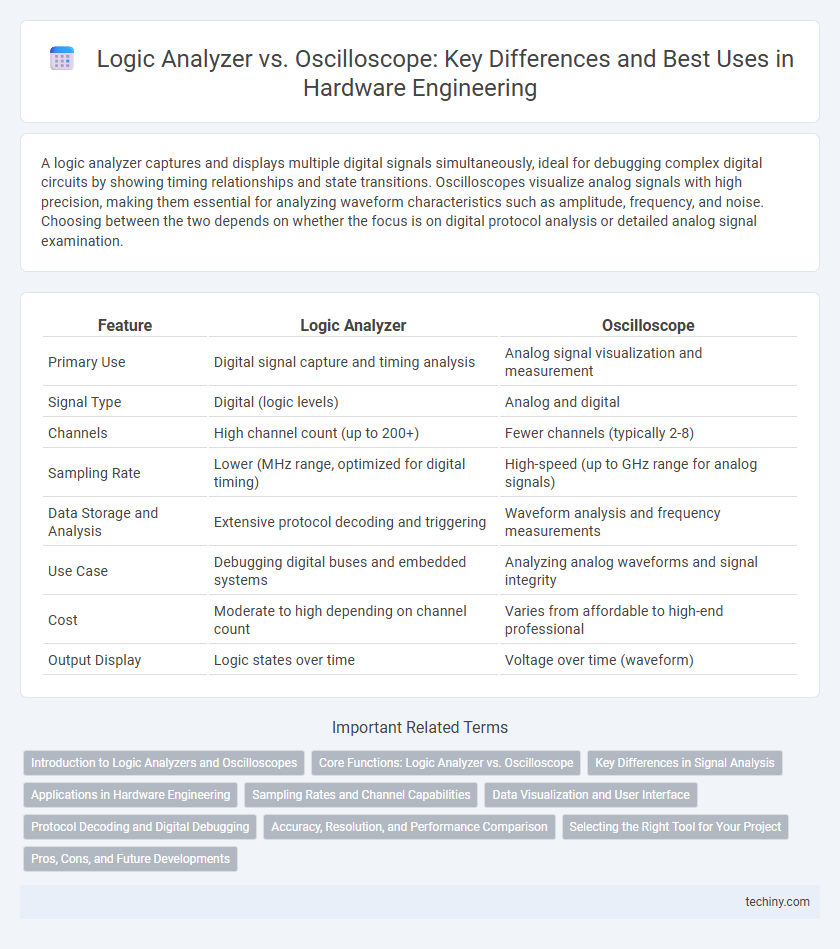
| Feature | Logic Analyzer | Oscilloscope |
|---|---|---|
| Primary Use | Digital signal capture and timing analysis | Analog signal visualization and measurement |
| Signal Type | Digital (logic levels) | Analog and digital |
| Channels | High channel count (up to 200+) | Fewer channels (typically 2-8) |
| Sampling Rate | Lower (MHz range, optimized for digital timing) | High-speed (up to GHz range for analog signals) |
| Data Storage and Analysis | Extensive protocol decoding and triggering | Waveform analysis and frequency measurements |
| Use Case | Debugging digital buses and embedded systems | Analyzing analog waveforms and signal integrity |
| Cost | Moderate to high depending on channel count | Varies from affordable to high-end professional |
| Output Display | Logic states over time | Voltage over time (waveform) |
Introduction to Logic Analyzers and Oscilloscopes
Logic analyzers and oscilloscopes are essential diagnostic tools in hardware engineering for analyzing electronic signals and system behavior. Logic analyzers capture and display multiple digital signals simultaneously, enabling detailed examination of timing relationships and digital protocol decoding. Oscilloscopes provide real-time visualization of analog waveforms, measuring voltage over time to identify signal integrity issues and transient anomalies in electronic circuits.
Core Functions: Logic Analyzer vs. Oscilloscope
Logic analyzers capture and display multiple digital signals simultaneously, enabling comprehensive timing analysis and state monitoring across complex digital circuits. Oscilloscopes measure and visualize analog voltage waveforms in real time, ideal for observing signal integrity and transient behaviors. While logic analyzers excel in decoding digital protocols and logic states, oscilloscopes provide detailed insight into signal amplitude and frequency characteristics.
Key Differences in Signal Analysis
Logic analyzers capture and analyze digital signals by sampling multiple channels simultaneously, providing detailed timing and state data essential for debugging complex digital circuits. Oscilloscopes visualize analog signals with continuous waveform representation, allowing engineers to observe voltage changes over time and measure signal integrity, noise, and distortion. The key difference lies in the logic analyzer's ability to decode digital protocols while oscilloscopes excel at real-time analog waveform visualization.
Applications in Hardware Engineering
Logic analyzers capture and analyze multiple digital signals simultaneously, making them essential for debugging complex digital circuits and verifying communication protocols in hardware engineering. Oscilloscopes visualize analog and digital waveforms in real-time, allowing engineers to inspect signal integrity, measure voltage levels, and diagnose timing issues in both analog and mixed-signal hardware designs. Combining both tools enhances comprehensive hardware testing, especially in embedded systems and integrated circuit development.
Sampling Rates and Channel Capabilities
Logic analyzers offer higher sampling rates, often exceeding 1 GHz, enabling precise capture of digital signals across multiple channels simultaneously, typically up to 100 or more. Oscilloscopes provide lower sampling rates, usually ranging from 100 MHz to several GHz, optimized for analog signal analysis with fewer channels, generally between 2 to 8. The choice depends on the complexity of signal analysis: logic analyzers excel in multi-channel digital signal timing and protocol debugging, while oscilloscopes are preferred for detailed waveform visualization and analog signal integrity.
Data Visualization and User Interface
Logic analyzers provide extensive multi-channel data visualization with the ability to display digital signals over extended timeframes, allowing efficient timing analysis and protocol decoding. Oscilloscopes excel in detailed waveform representation for analog signals, offering high-resolution graphical interfaces with real-time signal capture and measurement tools. User interfaces in logic analyzers prioritize digital event triggering and complex data filtering, while oscilloscopes focus on intuitive waveform manipulation and signal integrity diagnostics.
Protocol Decoding and Digital Debugging
Logic analyzers excel in protocol decoding by capturing and interpreting complex digital communication signals like SPI, I2C, and UART, providing detailed timing and data information essential for digital debugging. Oscilloscopes offer high-resolution waveform visualization, ideal for analyzing signal integrity and timing issues but lack extensive protocol decoding capabilities. Combining both tools enhances hardware engineers' ability to diagnose and troubleshoot digital systems effectively.
Accuracy, Resolution, and Performance Comparison
Logic analyzers provide superior accuracy in capturing digital signals with high channel counts, enabling detailed timing analysis across multiple lines, while oscilloscopes excel in signal resolution and waveform fidelity for analog signals, offering higher bandwidth and sample rates. Oscilloscopes typically deliver better vertical resolution, often 8 to 12 bits, compared to logic analyzers' 1-bit digital sampling, impacting the granularity of voltage measurement versus logical state detection. Performance-wise, logic analyzers are optimized for long-duration digital data capture with complex triggering options, whereas oscilloscopes offer real-time signal visualization and rapid transient response, making each instrument specialized for distinct diagnostic tasks in hardware engineering.
Selecting the Right Tool for Your Project
Selecting the right tool between a logic analyzer and an oscilloscope depends on your project's signal type and diagnostic needs. Logic analyzers excel at capturing and analyzing complex digital signals with multiple channels, providing precise timing and state information. Oscilloscopes are better suited for visualizing analog waveforms and signal integrity, making them essential for projects involving mixed-signal circuits or detailed voltage behavior.
Pros, Cons, and Future Developments
Logic analyzers excel at capturing and analyzing complex digital signals with multiple channels, offering detailed timing and state information crucial for debugging digital circuits, but they often come with higher costs and complexity compared to oscilloscopes. Oscilloscopes provide versatile, real-time visualization of analog and digital waveforms, making them ideal for a broad range of applications; however, they generally have limited channel counts and less capacity for comprehensive digital signal decoding. Future developments in both tools emphasize increased integration of AI for automated anomaly detection, enhanced multi-channel bandwidth, and improved user interfaces to streamline hardware debugging processes.
Logic analyzer vs Oscilloscope Infographic