Through-hole technology involves mounting electronic components by inserting their leads into drilled holes on a printed circuit board (PCB), providing strong mechanical bonds ideal for components subjected to mechanical stress. Surface-mount technology (SMT) places components directly onto the PCB surface, enabling higher component density, reduced board size, and enhanced performance in high-frequency applications. The choice between through-hole and SMT depends on factors such as assembly cost, mechanical durability, and design complexity.
Table of Comparison
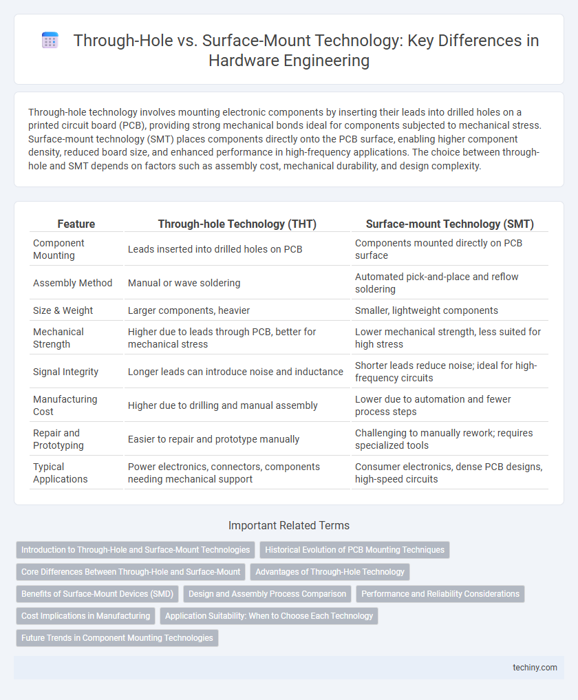
| Feature | Through-hole Technology (THT) | Surface-mount Technology (SMT) |
|---|---|---|
| Component Mounting | Leads inserted into drilled holes on PCB | Components mounted directly on PCB surface |
| Assembly Method | Manual or wave soldering | Automated pick-and-place and reflow soldering |
| Size & Weight | Larger components, heavier | Smaller, lightweight components |
| Mechanical Strength | Higher due to leads through PCB, better for mechanical stress | Lower mechanical strength, less suited for high stress |
| Signal Integrity | Longer leads can introduce noise and inductance | Shorter leads reduce noise; ideal for high-frequency circuits |
| Manufacturing Cost | Higher due to drilling and manual assembly | Lower due to automation and fewer process steps |
| Repair and Prototyping | Easier to repair and prototype manually | Challenging to manually rework; requires specialized tools |
| Typical Applications | Power electronics, connectors, components needing mechanical support | Consumer electronics, dense PCB designs, high-speed circuits |
Introduction to Through-Hole and Surface-Mount Technologies
Through-hole technology involves inserting electronic components with leads through pre-drilled holes on a printed circuit board (PCB), providing strong mechanical bonds ideal for heavy or high-stress applications. Surface-mount technology (SMT) places components directly onto the PCB surface, enabling higher component density and faster automated assembly processes. Both methods are fundamental in hardware engineering, with through-hole preferred for durability and prototyping, while SMT dominates mass production due to miniaturization and efficiency.
Historical Evolution of PCB Mounting Techniques
Through-hole mounting dominated early printed circuit board (PCB) assembly due to its robust mechanical connections and ease of manual soldering, primarily utilized in the 1950s and 1960s. Surface-mount technology (SMT) emerged in the late 1960s and gained widespread adoption by the 1980s, driven by the demand for miniaturization, higher circuit densities, and automated assembly processes. This transition marked a significant evolution in hardware engineering, enabling more compact, efficient, and reliable electronic devices.
Core Differences Between Through-Hole and Surface-Mount
Through-hole components feature leads inserted into drilled holes on the PCB and soldered on the opposite side, providing strong mechanical bonds ideal for heavy or high-stress applications. Surface-mount technology (SMT) involves directly mounting components onto the PCB surface, enabling smaller, lighter designs with higher component density and automated assembly. Key differences include assembly complexity, mechanical strength, and space efficiency, with through-hole favoring durability and SMT emphasizing miniaturization and production speed.
Advantages of Through-Hole Technology
Through-hole technology offers superior mechanical strength due to its leads passing through the PCB, making it ideal for components subject to physical stress or high power applications. It provides better reliability in harsh environments, such as automotive and aerospace systems, where robust connections are critical. Through-hole components also facilitate easier prototyping and manual soldering, which benefits small-scale production and repair tasks.
Benefits of Surface-Mount Devices (SMD)
Surface-Mount Devices (SMD) offer superior performance in hardware engineering due to their smaller size, which enables higher component density and more compact circuit designs. The automated assembly process for SMDs significantly reduces manufacturing costs and improves production speed compared to through-hole technology. Enhanced electrical performance and reliability arise from shorter lead lengths, minimizing parasitic inductance and capacitance in surface-mount components.
Design and Assembly Process Comparison
Through-hole components require drilling precise holes on the PCB, which adds complexity and time to the design and assembly process, making it suitable for prototypes and low-volume production. Surface-mount technology (SMT) enables compact and automated placement of smaller components directly onto the PCB surface, significantly improving assembly speed and allowing for higher component density. SMT designs reduce manual labor and rework costs, facilitating more efficient mass production and advanced circuit functionality.
Performance and Reliability Considerations
Through-hole components offer superior mechanical strength and are better suited for high-stress environments or heavy thermal cycling due to their leads passing through the PCB. Surface-mount technology (SMT) provides higher component density and improved electrical performance through shorter lead lengths, reducing parasitic inductance and capacitance. Reliability considerations favor through-hole for durability, while SMT enables enhanced signal integrity and faster production cycles in modern hardware engineering.
Cost Implications in Manufacturing
Through-hole technology generally incurs higher manufacturing costs due to increased labor, longer assembly times, and more material use for drilling and plating holes. Surface-mount technology (SMT) reduces production expenses by enabling automated placement, higher component density, and faster assembly cycles, which also lowers labor costs. The cost advantage of SMT becomes more pronounced in large-scale production runs and complex circuit designs.
Application Suitability: When to Choose Each Technology
Through-hole technology is ideal for applications requiring strong mechanical bonds and high durability, such as connectors, switches, and components exposed to mechanical stress or high power loads. Surface-mount technology suits high-density circuit boards, offering compact size and automated assembly benefits, making it optimal for consumer electronics, smartphones, and complex digital devices. Selection depends on factors including mechanical stress tolerance, board space constraints, and production volume demands.
Future Trends in Component Mounting Technologies
Future trends in component mounting technologies emphasize increased adoption of surface-mount technology (SMT) due to its compatibility with miniaturization and high-density circuit designs. Advanced through-hole techniques continue to evolve for applications demanding enhanced mechanical strength and thermal management, often integrated with SMT in hybrid assembly processes. Emerging developments in additive manufacturing and 3D component placement are poised to revolutionize traditional mounting, enabling more complex, multi-layered, and flexible hardware configurations.
Through-hole vs Surface-mount Infographic