The ground plane serves as a reference point for all signals and provides a low-impedance return path, reducing electromagnetic interference and noise in hardware systems. In contrast, the power plane distributes stable voltage levels across the circuit board, ensuring consistent power delivery to components. Proper separation and management of ground and power planes are essential for signal integrity and optimal hardware performance.
Table of Comparison
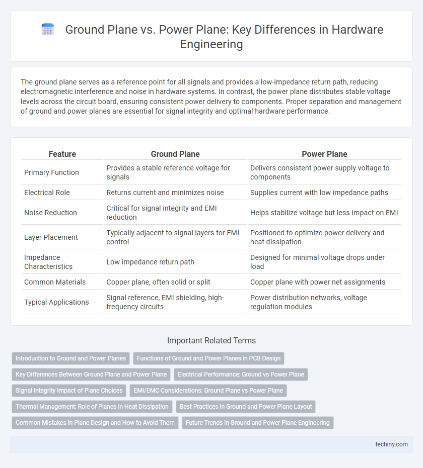
| Feature | Ground Plane | Power Plane |
|---|---|---|
| Primary Function | Provides a stable reference voltage for signals | Delivers consistent power supply voltage to components |
| Electrical Role | Returns current and minimizes noise | Supplies current with low impedance paths |
| Noise Reduction | Critical for signal integrity and EMI reduction | Helps stabilize voltage but less impact on EMI |
| Layer Placement | Typically adjacent to signal layers for EMI control | Positioned to optimize power delivery and heat dissipation |
| Impedance Characteristics | Low impedance return path | Designed for minimal voltage drops under load |
| Common Materials | Copper plane, often solid or split | Copper plane with power net assignments |
| Typical Applications | Signal reference, EMI shielding, high-frequency circuits | Power distribution networks, voltage regulation modules |
Introduction to Ground and Power Planes
Ground planes serve as a reference point for circuit voltages and provide a low-impedance return path for current, reducing electromagnetic interference (EMI) and improving signal integrity. Power planes distribute stable voltage levels across the printed circuit board (PCB), minimizing voltage drops and maintaining consistent power delivery to components. Both ground and power planes are essential in multilayer PCBs for enhancing electrical performance and thermal management.
Functions of Ground and Power Planes in PCB Design
Ground planes in PCB design serve as a reference point for signal voltages, providing a low-impedance path to minimize noise and electromagnetic interference, while ensuring signal integrity. Power planes distribute stable voltage levels across the board to various components, minimizing voltage drops and maintaining consistent power delivery. Both planes play critical roles in reducing signal crosstalk, improving thermal management, and enhancing overall circuit reliability.
Key Differences Between Ground Plane and Power Plane
Ground planes serve as a reference point for all signals and minimize electromagnetic interference by providing a common return path, while power planes distribute stable voltage levels to components, ensuring consistent power delivery. Ground planes typically cover larger PCB areas to reduce impedance and noise, whereas power planes are segmented and designed to handle specific current loads. The key difference lies in their function: ground planes manage signal integrity and noise reduction, whereas power planes focus on effective power distribution and voltage stability.
Electrical Performance: Ground vs Power Plane
A ground plane provides a stable reference voltage essential for reducing electromagnetic interference (EMI) and maintaining signal integrity by minimizing return path inductance. A power plane delivers regulated voltage to components but often introduces noise due to current fluctuations, which can degrade signal quality if not properly decoupled. Optimizing electrical performance involves careful layout to ensure the ground plane remains low-impedance and the power plane is adequately segmented with decoupling capacitors to minimize voltage ripple and electromagnetic interference.
Signal Integrity Impact of Plane Choices
The choice between ground planes and power planes significantly impacts signal integrity by influencing return current paths and electromagnetic interference (EMI) levels. Ground planes provide a low-impedance return path that minimizes noise and signal distortion, while power planes can introduce voltage fluctuations and increase crosstalk if not properly decoupled. Maintaining continuous ground planes beneath high-speed signal traces is essential for reducing signal reflection and preserving waveform integrity in hardware engineering designs.
EMI/EMC Considerations: Ground Plane vs Power Plane
Ground planes provide a low-impedance return path for signals, significantly reducing electromagnetic interference (EMI) by minimizing loop area and enhancing electromagnetic compatibility (EMC). Power planes, while essential for stable voltage delivery, can introduce noise coupling and increase EMI if not properly decoupled or segmented from ground planes. Careful layout design, including separation of power and ground planes and strategic placement of decoupling capacitors, optimizes EMI/EMC performance in hardware engineering.
Thermal Management: Role of Planes in Heat Dissipation
Ground planes serve as effective thermal sinks by distributing heat evenly across the PCB, reducing hotspots and improving overall device reliability. Power planes also contribute to thermal management by facilitating efficient current flow, which minimizes resistive heating and aids in dissipating localized thermal energy. Strategic placement of ground and power planes enhances heat dissipation, supporting optimal performance and longevity in high-power hardware designs.
Best Practices in Ground and Power Plane Layout
Optimal ground and power plane layout enhances signal integrity and reduces electromagnetic interference in hardware engineering. Maintaining continuous, unbroken ground planes minimizes noise and provides a stable reference for components, while proper placement of power planes with adequate decoupling capacitors ensures clean and stable voltage distribution. Segmentation of power and ground planes should be avoided to prevent ground loops and voltage drops, and careful alignment of return currents on the ground plane under high-speed signals is critical for minimizing loop area and radiated emissions.
Common Mistakes in Plane Design and How to Avoid Them
Common mistakes in ground plane and power plane design include inadequate separation, resulting in noise coupling and signal integrity issues, and insufficient layer stacking, which can lead to EMI problems and voltage drops. Avoid these errors by maintaining continuous, unbroken ground planes, optimizing plane thickness for current capacity, and ensuring proper decoupling capacitor placement near power pins. Careful impedance control and minimizing plane splits help improve overall PCB performance and reliability in hardware engineering.
Future Trends in Ground and Power Plane Engineering
Future trends in ground and power plane engineering emphasize enhanced signal integrity and electromagnetic compatibility through advanced materials like low-loss laminates and embedded capacitance layers. Integration of adaptive impedance control and dynamic power distribution networks using AI-driven design tools improves noise reduction and energy efficiency in high-speed PCBs. Emerging technologies also explore 3D integration with multi-layer planes to optimize space utilization while supporting higher frequency demands in next-generation hardware systems.
Ground Plane vs Power Plane Infographic