Optimizing track width and track spacing is crucial in hardware engineering to balance electrical performance and manufacturability. Wider tracks reduce resistance and improve current-carrying capacity, while adequate spacing prevents crosstalk and short circuits in high-density PCB designs. Precise control of these parameters ensures signal integrity and reliable device operation under varying thermal and electrical conditions.
Table of Comparison
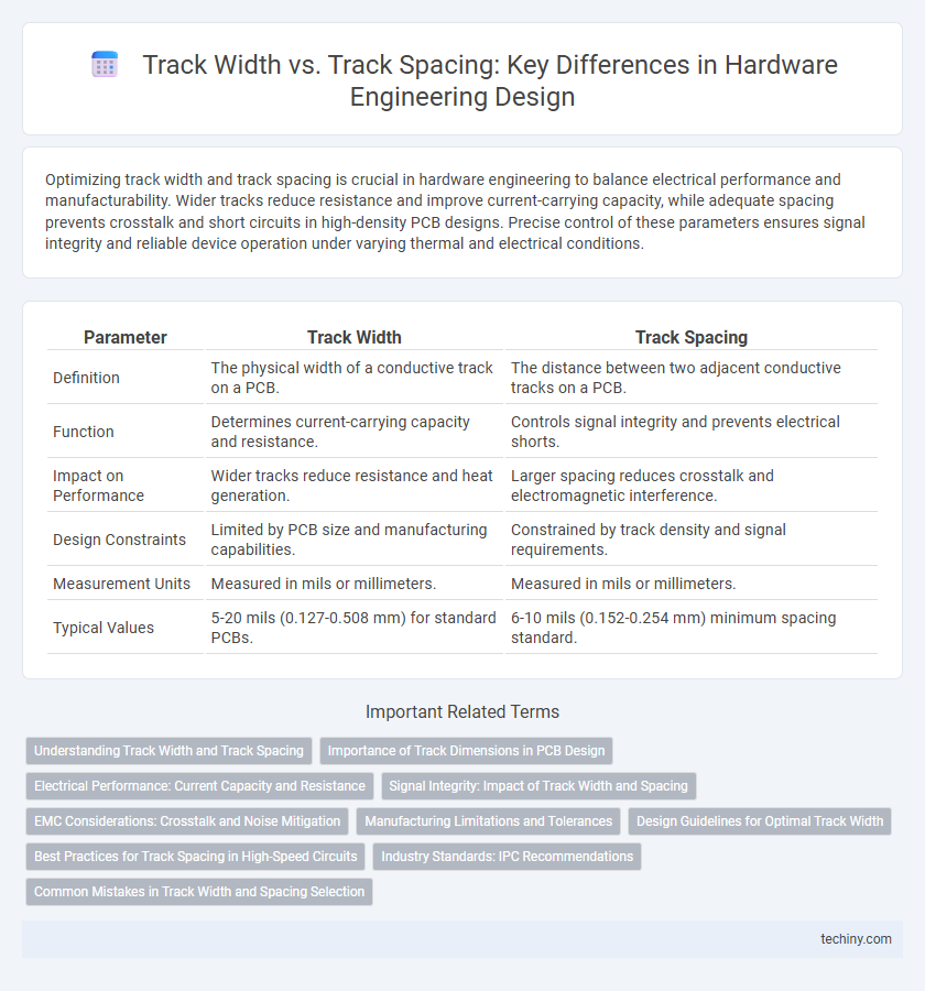
| Parameter | Track Width | Track Spacing |
|---|---|---|
| Definition | The physical width of a conductive track on a PCB. | The distance between two adjacent conductive tracks on a PCB. |
| Function | Determines current-carrying capacity and resistance. | Controls signal integrity and prevents electrical shorts. |
| Impact on Performance | Wider tracks reduce resistance and heat generation. | Larger spacing reduces crosstalk and electromagnetic interference. |
| Design Constraints | Limited by PCB size and manufacturing capabilities. | Constrained by track density and signal requirements. |
| Measurement Units | Measured in mils or millimeters. | Measured in mils or millimeters. |
| Typical Values | 5-20 mils (0.127-0.508 mm) for standard PCBs. | 6-10 mils (0.152-0.254 mm) minimum spacing standard. |
Understanding Track Width and Track Spacing
Track width refers to the physical width of a conductive pathway on a printed circuit board (PCB), which impacts current capacity and signal integrity. Track spacing is the distance between adjacent conductive paths, influencing dielectric isolation and reducing risk of short circuits or crosstalk. Correctly optimizing track width and spacing is essential for ensuring electrical performance and reliability in hardware designs.
Importance of Track Dimensions in PCB Design
Precise track width and track spacing in PCB design are crucial for ensuring proper current capacity and signal integrity. Optimal track width prevents excessive heat buildup while appropriate spacing reduces the risk of short circuits and electromagnetic interference. Adhering to these dimensions improves overall reliability and performance in complex hardware engineering projects.
Electrical Performance: Current Capacity and Resistance
Track width directly influences electrical performance by determining current capacity, where wider tracks reduce resistance and heat buildup, enhancing efficiency in PCB designs. Conversely, track spacing primarily affects signal integrity and crosstalk rather than current carrying capability, with smaller spacing increasing the risk of electrical interference. Optimizing track width and spacing balances minimizing resistance and maintaining signal quality to ensure reliable hardware functionality.
Signal Integrity: Impact of Track Width and Spacing
Track width and track spacing critically influence signal integrity in hardware engineering by affecting impedance and crosstalk levels on printed circuit boards (PCBs). Wider tracks reduce resistance and signal attenuation, enhancing high-frequency performance, while narrower spacing increases capacitive coupling, leading to potential signal distortion and electromagnetic interference (EMI). Optimizing the balance between track width and spacing is essential to minimize signal reflection and maintain consistent impedance for reliable high-speed data transmission.
EMC Considerations: Crosstalk and Noise Mitigation
Track width and track spacing play critical roles in controlling crosstalk and electromagnetic interference (EMI) in high-speed PCB designs. Wider track spacing reduces capacitive coupling between adjacent traces, thereby minimizing noise coupling and improving signal integrity. Optimizing track width also decreases resistance and inductance, which helps lower radiated emissions and mitigates crosstalk effects in sensitive hardware engineering applications.
Manufacturing Limitations and Tolerances
Track width and track spacing are critical parameters in hardware engineering that directly impact manufacturing tolerances and capabilities. Narrow track widths enhance circuit density but increase the risk of defects due to process variations, while wider track spacing reduces crosstalk and improves signal integrity but limits miniaturization. Manufacturing limitations, such as photolithography resolution and etching precision, impose strict constraints on achievable track widths and spacings, necessitating careful optimization to balance performance and yield.
Design Guidelines for Optimal Track Width
Optimal track width in hardware engineering ensures reliable current carrying capacity and minimizes voltage drop in PCB design. Track spacing must complement width to prevent crosstalk and electrical interference, adhering to IPC-2221 standards for safety and manufacturability. Balancing track width with thermal relief and signal integrity requirements enhances overall circuit performance and longevity.
Best Practices for Track Spacing in High-Speed Circuits
Optimal track spacing in high-speed circuits minimizes crosstalk and signal integrity issues by maintaining sufficient isolation between adjacent traces, typically following the rule of maintaining spacing equal to or greater than the trace width. High-frequency signals demand increased spacing to reduce electromagnetic interference (EMI) and preserve the characteristic impedance of transmission lines. Implementing controlled impedance with precise track width and spacing aligned to PCB stack-up and dielectric properties ensures reliable high-speed signal transmission and minimizes signal degradation.
Industry Standards: IPC Recommendations
Industry standards such as IPC-2221 provide detailed guidelines on track width and track spacing to ensure signal integrity and manufacturability in PCB design. Track width is determined based on current carrying capacity, while track spacing is optimized to prevent electrical shorts and crosstalk, adhering to minimum clearance values specified by IPC. Following these IPC recommendations enhances reliability and compliance with industry best practices in hardware engineering.
Common Mistakes in Track Width and Spacing Selection
Common mistakes in track width and spacing selection include underestimating current capacity requirements, leading to tracks that overheat or fail prematurely. Ignoring manufacturing tolerances can result in spacing that causes short circuits or signal interference, compromising board reliability. Failing to follow industry design rules such as IPC-2221 standards increases the risk of electrical failures and reduces PCB longevity.
Track Width vs Track Spacing Infographic