PCB (Printed Circuit Board) serves as the foundational platform that mechanically supports and electrically connects electronic components using conductive pathways, while PCBA (Printed Circuit Board Assembly) refers to the completed product after mounting and soldering all necessary components onto the PCB. The PCBA process includes soldering techniques, component placement, and quality testing, which ensure the final device's functionality and reliability. Understanding the distinction between PCB and PCBA is critical for hardware engineers to optimize production workflows and achieve effective electronic device performance.
Table of Comparison
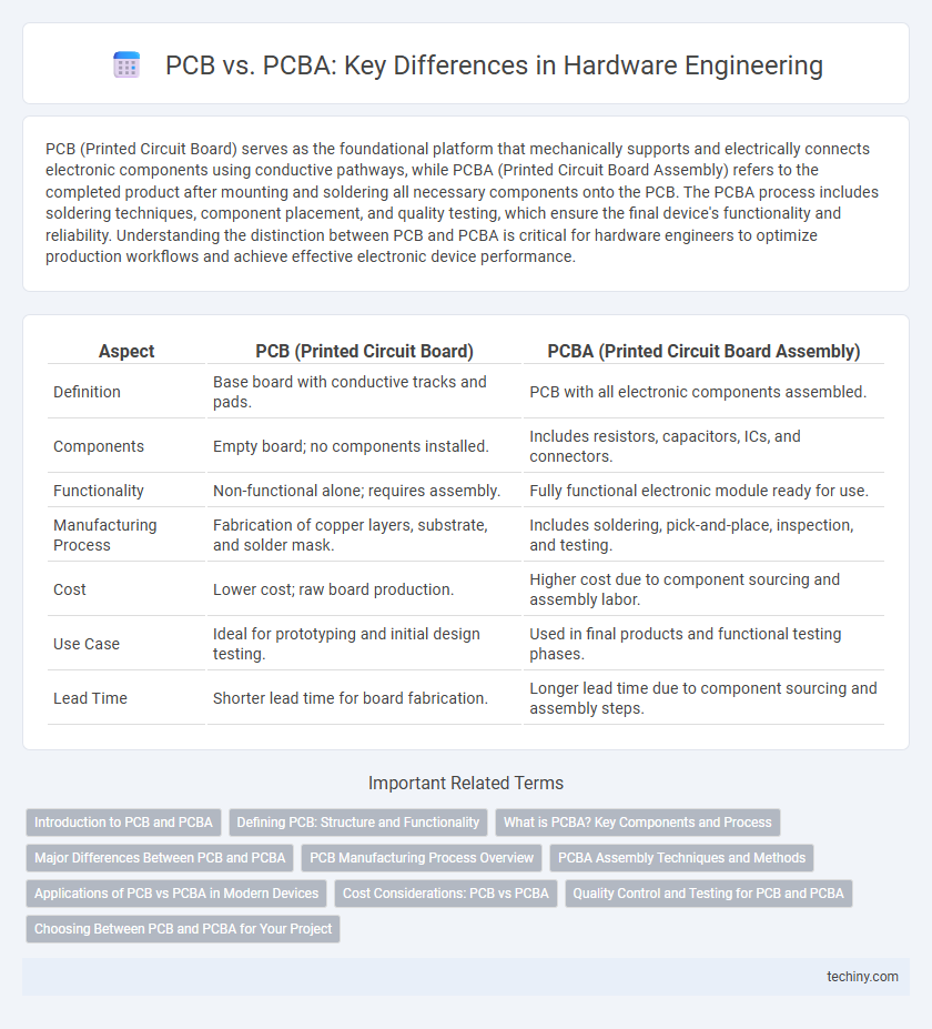
| Aspect | PCB (Printed Circuit Board) | PCBA (Printed Circuit Board Assembly) |
|---|---|---|
| Definition | Base board with conductive tracks and pads. | PCB with all electronic components assembled. |
| Components | Empty board; no components installed. | Includes resistors, capacitors, ICs, and connectors. |
| Functionality | Non-functional alone; requires assembly. | Fully functional electronic module ready for use. |
| Manufacturing Process | Fabrication of copper layers, substrate, and solder mask. | Includes soldering, pick-and-place, inspection, and testing. |
| Cost | Lower cost; raw board production. | Higher cost due to component sourcing and assembly labor. |
| Use Case | Ideal for prototyping and initial design testing. | Used in final products and functional testing phases. |
| Lead Time | Shorter lead time for board fabrication. | Longer lead time due to component sourcing and assembly steps. |
Introduction to PCB and PCBA
A Printed Circuit Board (PCB) is a foundational hardware component consisting of conductive pathways etched from copper sheets laminated onto a non-conductive substrate, enabling the mechanical support and electrical connection of electronic components. Printed Circuit Board Assembly (PCBA) refers to the process of soldering and mounting electronic components onto the bare PCB, transforming it into a functional electronic assembly. PCBA incorporates surface mount technology (SMT) or through-hole technology (THT) to create integrated circuits essential for hardware devices.
Defining PCB: Structure and Functionality
A Printed Circuit Board (PCB) is a rigid or flexible substrate that mechanically supports and electrically connects electronic components using conductive tracks, pads, and other features etched from copper sheets laminated onto a non-conductive base. PCBs serve as the foundational platform in electronic devices, facilitating signal routing and component integration through multiple layers optimized for electromagnetic compatibility and thermal management. The design includes layers such as signal, power, and ground planes, ensuring reliable functionality and mechanical integrity within complex hardware systems.
What is PCBA? Key Components and Process
PCBA (Printed Circuit Board Assembly) involves mounting electronic components onto a bare PCB through processes like soldering and inspection to create a functional electronic assembly. Key components of PCBA include resistors, capacitors, integrated circuits, connectors, and solder paste. The process begins with solder paste application, followed by component placement, reflow soldering, inspection, and testing to ensure electrical connectivity and functionality.
Major Differences Between PCB and PCBA
PCB (Printed Circuit Board) serves as the foundational platform providing mechanical support and electrical connections for electronic components. PCBA (Printed Circuit Board Assembly) refers to the complete board after components like resistors, capacitors, and ICs have been soldered onto the PCB. The major difference lies in PCB being the bare board, while PCBA includes the populated and functional assembly ready for integration into electronic devices.
PCB Manufacturing Process Overview
The PCB manufacturing process involves multiple precise steps including substrate preparation, patterning through photolithography, etching to remove unwanted copper, and layering for multi-layer boards. Automated optical inspection (AOI) and electrical testing ensure quality and functionality before the PCB is shipped. In contrast, PCBA includes the assembly of electronic components on the fabricated PCB, requiring soldering techniques such as surface-mount technology (SMT) and through-hole mounting.
PCBA Assembly Techniques and Methods
PCBA assembly techniques encompass surface mount technology (SMT), through-hole technology (THT), and mixed technology, each optimizing component placement and soldering precision on printed circuit boards. Automated pick-and-place machines enhance efficiency and accuracy during SMT, while wave soldering and reflow soldering ensure robust electrical connections and mechanical stability. Inspection methods such as automated optical inspection (AOI) and X-ray analysis validate solder joint quality and component alignment, reducing defects in the final PCBA product.
Applications of PCB vs PCBA in Modern Devices
Printed Circuit Boards (PCBs) serve as fundamental platforms providing mechanical support and electrical connectivity for electronic components in devices such as computers, smartphones, and automotive systems. Printed Circuit Board Assemblies (PCBAs), which integrate PCBs with mounted and soldered components, enable fully functional modules essential for modern electronics including IoT devices, medical equipment, and aerospace technology. The distinction lies in PCBs being the base structure while PCBAs represent complete operational units driving advanced hardware applications.
Cost Considerations: PCB vs PCBA
The cost of a Printed Circuit Board (PCB) primarily involves raw materials like copper, laminate, and manufacturing processes such as etching and drilling. In contrast, the cost of Printed Circuit Board Assembly (PCBA) includes the PCB cost plus expenses related to component procurement, soldering, testing, and inspection. Assembly costs vary significantly depending on component complexity, volume, and labor or automation methods used, making PCBA generally more expensive than bare PCB production.
Quality Control and Testing for PCB and PCBA
Quality control for PCBs involves rigorous inspection of the substrate, copper layers, and traces to prevent defects like shorts or open circuits, using techniques such as automated optical inspection (AOI) and electrical testing. In contrast, PCBA quality control encompasses both the PCB inspection and the thorough testing of assembled components, including in-circuit testing (ICT) and functional testing, to ensure solder joint integrity and component functionality. Effective testing protocols for PCBA minimize failures in final products by verifying both the bare board quality and the accuracy of component placement and soldering processes.
Choosing Between PCB and PCBA for Your Project
Selecting between PCB and PCBA depends on your project's complexity and assembly requirements. A PCB (Printed Circuit Board) provides the foundational substrate for electronic components, while PCBA (PCB Assembly) includes the fully assembled board with soldered components, ready for testing and integration. Opting for PCBA accelerates development by eliminating manual component mounting, whereas choosing only a PCB offers flexibility for custom, in-house assembly and prototyping.
PCB vs PCBA Infographic