Open-drain outputs allow multiple devices to share a line for communication by pulling it low, relying on external pull-up resistors to achieve a high state, which makes them ideal for wired-AND logic and bus systems. Push-pull outputs actively drive the line both high and low, offering faster switching speeds and stronger signal integrity but require careful design to avoid contention. Choosing between open-drain and push-pull depends on the application's need for bus sharing flexibility versus speed and drive strength.
Table of Comparison
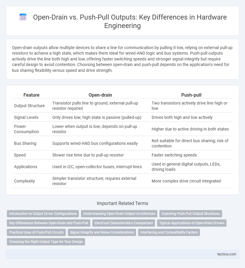
| Feature | Open-drain | Push-pull |
|---|---|---|
| Output Structure | Transistor pulls line to ground; external pull-up resistor required | Two transistors actively drive line high or low |
| Signal Levels | Only drives low; high state is passive (pulled-up) | Drives both high and low actively |
| Power Consumption | Lower when output is low; depends on pull-up resistor | Higher due to active driving in both states |
| Bus Sharing | Supports wired-AND bus configurations easily | Not suitable for direct bus sharing; risk of contention |
| Speed | Slower rise time due to pull-up resistor | Faster switching speeds |
| Applications | Used in I2C, open-collector buses, interrupt lines | Used in general digital outputs, LEDs, driving loads |
| Complexity | Simpler transistor structure; requires external resistor | More complex drive circuit integrated |
Introduction to Output Driver Configurations
Open-drain and push-pull output driver configurations are fundamental in hardware engineering for controlling signal transmission. Open-drain outputs can only sink current, requiring an external pull-up resistor to achieve a high logic level, making them ideal for wired-AND or multi-drop bus applications. Push-pull drivers actively drive both high and low states, enabling faster switching speeds and stronger signal integrity in point-to-point communication.
Understanding Open-Drain Output Architecture
Open-drain output architecture uses a transistor to connect the output pin to ground, allowing multiple devices to share the same line without risk of damage. This design relies on an external pull-up resistor to define the high logic level, enabling flexible voltage interfacing and wired-AND configurations. Understanding open-drain outputs is crucial for hardware engineers working with communication protocols like I2C or implementing interrupt lines.
Exploring Push-Pull Output Structures
Push-pull output structures in hardware engineering use complementary transistors to drive the output line actively high and low, providing faster switching speeds and stronger drive capabilities compared to open-drain configurations. This output type reduces power consumption and minimizes voltage drops, making it ideal for high-speed digital signal transmission and precise voltage level control. Push-pull circuits are commonly implemented in microcontrollers, communication interfaces, and power drivers where robust and efficient signal driving is critical.
Key Differences Between Open-Drain and Push-Pull
Open-drain outputs use a transistor to pull the line low, requiring an external pull-up resistor to drive the line high, enabling wired-AND configurations and multiple devices to share the bus without contention. Push-pull outputs actively drive both high and low states, offering faster switching speeds and stronger drive capabilities suitable for single-master communication. The choice between open-drain and push-pull impacts power consumption, signal integrity, and bus arbitration in hardware design.
Electrical Characteristics Comparison
Open-drain outputs allow multiple devices to share a line for wired-AND logic by sinking current when active and relying on external pull-up resistors to achieve a high state, resulting in slower rise times and higher power consumption during transitions. Push-pull outputs actively drive both high and low states using complementary transistors, providing faster switching speeds, stronger drive capability, and reduced power dissipation under typical load conditions. Electrical characteristics such as output impedance, switching speed, noise immunity, and power efficiency differ significantly, with push-pull offering superior performance in high-speed digital circuits while open-drain is favored for bus arbitration and level shifting applications.
Typical Applications of Open-Drain Drivers
Open-drain drivers are commonly used in bus systems like I2C and 1-Wire, where multiple devices share a single communication line and require a wired-AND configuration for safe data transmission. They are ideal for level shifting between different voltage domains and for implementing interrupt signals that multiple devices can assert without conflict. Open-drain outputs also facilitate fault-tolerant designs by allowing external pull-up resistors to define the signal level, ensuring reliable communication in noisy environments.
Practical Uses of Push-Pull Circuits
Push-pull circuits are widely used in hardware engineering for driving loads that require efficient power delivery and fast switching, such as in motor drivers and audio amplifiers. These circuits provide both sourcing and sinking current capabilities, enabling better control over the output voltage levels and minimizing power dissipation. Their ability to drive signals with low distortion and high fidelity makes push-pull configurations essential in communication interfaces and power management systems.
Signal Integrity and Noise Considerations
Open-drain outputs allow multiple devices to share a line without contention, reducing signal interference in wired-AND configurations but can suffer from slower signal rise times and increased susceptibility to noise due to pull-up resistors. Push-pull drivers actively drive both high and low states, providing faster transitions and stronger noise immunity, enhancing signal integrity in high-speed digital circuits. Careful selection between open-drain and push-pull configurations depends on the trade-offs between bus contention avoidance and the need for fast, clean signal transitions in the hardware design.
Interfacing and Compatibility Factors
Open-drain configurations allow multiple devices to share a line by pulling it low, requiring an external pull-up resistor to achieve a high logic level, which enhances compatibility in bus systems like I2C. Push-pull outputs actively drive the line both high and low, providing faster switching speeds and stronger signal integrity, ideal for direct point-to-point interfacing. Selecting between open-drain and push-pull depends on factors such as bus architecture, noise margin, power consumption, and the need for wired-AND logic compatibility.
Choosing the Right Output Type for Your Design
Open-drain outputs are ideal for wired-AND logic and level shifting in mixed-voltage environments, offering flexibility in multi-device communication but requiring an external pull-up resistor. Push-pull outputs provide stronger drive capability and faster switching speeds, making them suitable for driving loads that need rapid transitions and precise voltage levels. Selecting between open-drain and push-pull depends on factors such as load type, signal integrity requirements, and system voltage compatibility in hardware design.
Open-drain vs Push-pull Infographic