Inductive coupling in hardware engineering relies on magnetic fields to transfer energy or signals between circuits without direct electrical connections, making it ideal for wireless power transfer and transformers. Capacitive coupling uses electric fields between conductive plates to transmit signals or power, often employed in high-frequency circuits to block DC components while allowing AC signals to pass. Understanding the differences in frequency response, interference susceptibility, and application suitability is crucial for optimizing circuit design and ensuring efficient signal integrity.
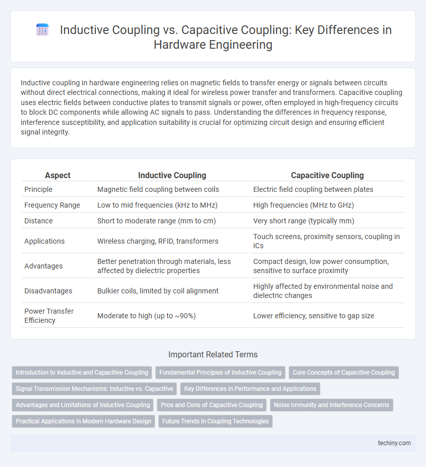
Table of Comparison
| Aspect | Inductive Coupling | Capacitive Coupling |
|---|---|---|
| Principle | Magnetic field coupling between coils | Electric field coupling between plates |
| Frequency Range | Low to mid frequencies (kHz to MHz) | High frequencies (MHz to GHz) |
| Distance | Short to moderate range (mm to cm) | Very short range (typically mm) |
| Applications | Wireless charging, RFID, transformers | Touch screens, proximity sensors, coupling in ICs |
| Advantages | Better penetration through materials, less affected by dielectric properties | Compact design, low power consumption, sensitive to surface proximity |
| Disadvantages | Bulkier coils, limited by coil alignment | Highly affected by environmental noise and dielectric changes |
| Power Transfer Efficiency | Moderate to high (up to ~90%) | Lower efficiency, sensitive to gap size |
Introduction to Inductive and Capacitive Coupling
Inductive coupling occurs when a varying magnetic field induces a voltage across a nearby conductor, commonly used in transformers and wireless power transfer. Capacitive coupling involves the transfer of energy through electric fields between conductive elements separated by an insulator, frequently seen in printed circuit board (PCB) crosstalk and signal interference. Understanding the distinct electromagnetic principles behind inductive and capacitive coupling is crucial for minimizing noise and optimizing signal integrity in hardware engineering designs.
Fundamental Principles of Inductive Coupling
Inductive coupling operates on the fundamental principle of electromagnetic induction, where a time-varying current in a primary coil generates a magnetic field that induces a voltage in a secondary coil placed within its vicinity. This magnetic flux linkage enables wireless energy transfer or signal transmission without direct electrical contact, making it essential in transformers, wireless chargers, and RFID systems. The efficiency of inductive coupling depends on coil geometry, distance, frequency, and core material permeability, which influence mutual inductance and coupling coefficient.
Core Concepts of Capacitive Coupling
Capacitive coupling involves the transfer of energy between circuits through the electric field formed between two conductive plates separated by a dielectric material. This mechanism relies on the principle that varying voltage in one conductor induces a displacement current in the adjacent conductor without direct electrical contact. Core concepts include the capacitance value determined by plate area, separation distance, and dielectric constant, which influence signal integrity and noise susceptibility in hardware design.
Signal Transmission Mechanisms: Inductive vs. Capacitive
Inductive coupling transmits signals through magnetic fields generated by current flow in coils, enabling efficient energy transfer over short distances with minimal direct contact. Capacitive coupling relies on electric fields between conductive plates, facilitating signal transmission by displacement currents across dielectric gaps, often used in high-frequency applications with low power loss. Signal integrity in inductive coupling is influenced by coil design and magnetic permeability, while capacitive coupling depends on plate geometry and dielectric properties.
Key Differences in Performance and Applications
Inductive coupling offers superior performance for wireless power transfer and signal isolation in high-frequency circuits due to its magnetic field-based energy transfer, while capacitive coupling excels in low-frequency applications and signal transmission through electric field interactions. Inductive coupling provides better immunity to electromagnetic interference (EMI) and supports longer distances between coupled components, making it ideal for transformers and RFID systems. Capacitive coupling, with its lower power loss and compact design, is preferred in integrated circuits for signal integrity and filtering applications requiring minimal physical spacing.
Advantages and Limitations of Inductive Coupling
Inductive coupling offers the advantage of wireless energy transfer over short distances with minimal physical contact, enhancing device durability and reducing wear in hardware engineering applications. Its limitations include sensitivity to alignment and distance between coils, leading to reduced efficiency with misalignment or increased separation. Electromagnetic interference and limited range further constrain the reliability and scalability of inductive coupling systems in complex hardware environments.
Pros and Cons of Capacitive Coupling
Capacitive coupling offers advantages such as low power consumption and high-frequency signal transmission, making it ideal for integrated circuits and sensor applications. However, it is sensitive to electromagnetic interference and requires precise control of the coupling capacitance to maintain signal integrity. Its performance can degrade in environments with high noise levels or varying temperatures, posing challenges for robust hardware design.
Noise Immunity and Interference Concerns
Inductive coupling generates noise through magnetic fields, often causing interference in nearby circuits with high-frequency signals. Capacitive coupling induces noise via electric fields and is more sensitive to high-impedance nodes, making it critical to control parasitic capacitances for noise immunity. Effective hardware engineering employs shielding techniques and careful PCB layout to minimize both inductive and capacitive coupling, enhancing overall system noise immunity and reducing interference concerns.
Practical Applications in Modern Hardware Design
Inductive coupling is widely used in wireless power transfer systems, such as Qi-enabled charging pads for smartphones and electric vehicle charging stations, leveraging magnetic fields for efficient energy transmission. Capacitive coupling finds practical application in touchscreens and signal isolation in high-frequency circuits by utilizing electric fields to transmit signals without direct electrical contact. Both coupling methods enhance circuit integration and noise reduction in modern hardware design, optimizing performance in compact and complex electronic devices.
Future Trends in Coupling Technologies
Future trends in coupling technologies emphasize hybrid approaches combining inductive and capacitive coupling to enhance signal integrity and power efficiency in hardware engineering. Innovations in materials science, such as metamaterials and nanostructures, enable more precise electromagnetic field control, reducing interference and increasing data transfer rates. Integration of AI-driven adaptive coupling circuits promises real-time optimization of coupling parameters, fostering advancements in wireless power transfer and high-speed communication devices.
inductive coupling vs capacitive coupling Infographic