Pull-up resistors connect a signal line to a high voltage level, ensuring the line reads logic high when no active device drives it low. Pull-down resistors connect the signal line to ground, guaranteeing a logic low state in the absence of other inputs. Selecting between pull-up and pull-down depends on the desired default logic state and system voltage compatibility.
Table of Comparison
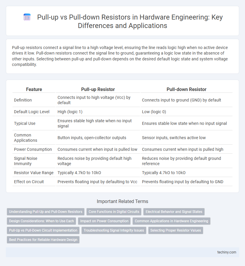
| Feature | Pull-up Resistor | Pull-down Resistor |
|---|---|---|
| Definition | Connects input to high voltage (Vcc) by default | Connects input to ground (GND) by default |
| Default Logic Level | High (logic 1) | Low (logic 0) |
| Typical Use | Ensures stable high state when no input signal | Ensures stable low state when no input signal |
| Common Applications | Button inputs, open-collector outputs | Sensor inputs, switches active low |
| Power Consumption | Consumes current when input is pulled low | Consumes current when input is pulled high |
| Signal Noise Immunity | Reduces noise by providing default high voltage | Reduces noise by providing default ground reference |
| Resistor Value Range | Typically 4.7kO to 10kO | Typically 4.7kO to 10kO |
| Effect on Circuit | Prevents floating input by defaulting to Vcc | Prevents floating input by defaulting to GND |
Understanding Pull-Up and Pull-Down Resistors
Pull-up and pull-down resistors are essential in hardware engineering to establish defined voltage levels on digital input pins, preventing floating and unpredictable signals. A pull-up resistor connects the input to a high logic level (typically Vcc), ensuring the pin reads as "1" when not actively driven, while a pull-down resistor connects the input to ground, ensuring a "0" reading in an idle state. Choosing appropriate resistor values, usually between 1kO and 10kO, balances power consumption and noise immunity for stable logic input detection.
Core Functions in Digital Circuits
Pull-up resistors connect a signal line to a positive voltage supply, ensuring a default HIGH logic level in digital circuits, while pull-down resistors link the line to ground, establishing a default LOW logic level. These components stabilize input signals by preventing floating states that can cause unpredictable behavior in microcontrollers and logic gates. Proper implementation of pull-up and pull-down resistors is crucial for maintaining signal integrity and reliable digital circuit operation.
Electrical Behavior and Signal States
Pull-up resistors connect the input pin to a high voltage level, ensuring a default logic high state when the switch or input device is open, which prevents floating signals and reduces noise susceptibility. Pull-down resistors, conversely, connect the input to ground, establishing a default logic low state and stabilizing the signal line by preventing undefined intermediate voltage levels. The choice between pull-up and pull-down affects the electrical behavior by determining the default voltage level and signal integrity in digital circuits.
Design Considerations: When to Use Each
Pull-up resistors are ideal in open-drain or open-collector circuits where a defined logic high level is needed when the switch or transistor is off, preventing floating inputs and ensuring stable signal states. Pull-down resistors are preferred when the default state should be logic low, particularly in push-button inputs or where external circuitry actively drives the signal high. Design considerations include power consumption, input impedance, noise susceptibility, and the specific logic family requirements to determine whether pull-up or pull-down configuration optimally maintains signal integrity and system reliability.
Impact on Power Consumption
Pull-up resistors typically increase power consumption by continuously drawing current when the connected line is pulled low, whereas pull-down resistors minimize power usage by only allowing current flow when the line is driven high. Choosing between pull-up and pull-down resistors depends on the circuit's logic level requirements and the desired power efficiency, with pull-down configurations generally preferred in low-power applications. Optimizing resistor values can further reduce unnecessary current draw, directly impacting overall energy consumption in hardware design.
Common Applications in Hardware Engineering
Pull-up resistors are commonly used in digital circuits to ensure a defined voltage level, typically pulling a pin to a high logical state when no active device is driving it, which is essential for inputs like microcontroller pins or switch interfaces. Pull-down resistors serve the opposite function by maintaining a low logical state when no active signal is present, frequently applied in transistor gate control and logic IC inputs where a default ground reference is required. Both are critical in preventing floating nodes, noise, and undefined states, ensuring stable and reliable operation in embedded systems and digital logic designs.
Pull-Up vs Pull-Down Circuit Implementation
Pull-up circuits connect input lines to a high voltage level (usually VCC) through a resistor, ensuring the input reads as a logical high when no active devices drive the line, while pull-down circuits connect inputs to ground via a resistor to maintain a logical low state. Pull-up resistor values typically range from 1kO to 10kO, balancing power consumption and noise immunity, whereas pull-down resistors often use similar values but have less common usage depending on the logic family and application requirements. Implementing pull-up or pull-down circuits affects input pin stability, noise margins, and power efficiency, making resistor value selection and circuit placement critical in microcontroller interfaces and digital logic designs.
Troubleshooting Signal Integrity Issues
Pull-up and pull-down resistors play a critical role in maintaining defined voltage levels on digital inputs to prevent floating signals and reduce noise susceptibility. Troubleshooting signal integrity issues often involves checking for incorrect resistor values or placement, as improper pull-up or pull-down configurations can cause erratic switching, increased electromagnetic interference (EMI), or logic level ambiguities. Utilizing tools like oscilloscopes to measure signal waveforms and verifying resistor connections against circuit schematics help identify and resolve signal integrity problems quickly.
Selecting Proper Resistor Values
Selecting proper resistor values in pull-up versus pull-down configurations impacts signal integrity and power consumption in hardware engineering. Pull-up resistors typically range from 1kO to 10kO to ensure a stable HIGH voltage level without excessive current draw, while pull-down resistors use similar ranges to maintain a stable LOW state. Choosing resistor values depends on input pin characteristics, desired noise immunity, and overall circuit speed requirements to optimize performance and minimize power loss.
Best Practices for Reliable Hardware Design
Pull-up resistors are commonly used to ensure a defined logic high level on input pins, preventing floating states that cause noise and unreliable operation. Pull-down resistors establish a default logic low level, useful when ensuring circuits reset to ground without interference. Selecting the proper resistor value--typically between 4.7kO and 10kO--balances power consumption and signal integrity, promoting consistent and stable hardware behavior in digital circuits.
Pull-up vs Pull-down Infographic