Active High signals activate a hardware component when the signal is at a high voltage level, typically representing a logic '1'. Active Low signals trigger the component when the signal is at a low voltage level, usually corresponding to a logic '0'. Understanding the distinction between Active High and Active Low is essential for designing reliable circuits and ensuring proper interfacing with integrated circuits and digital logic devices.
Table of Comparison
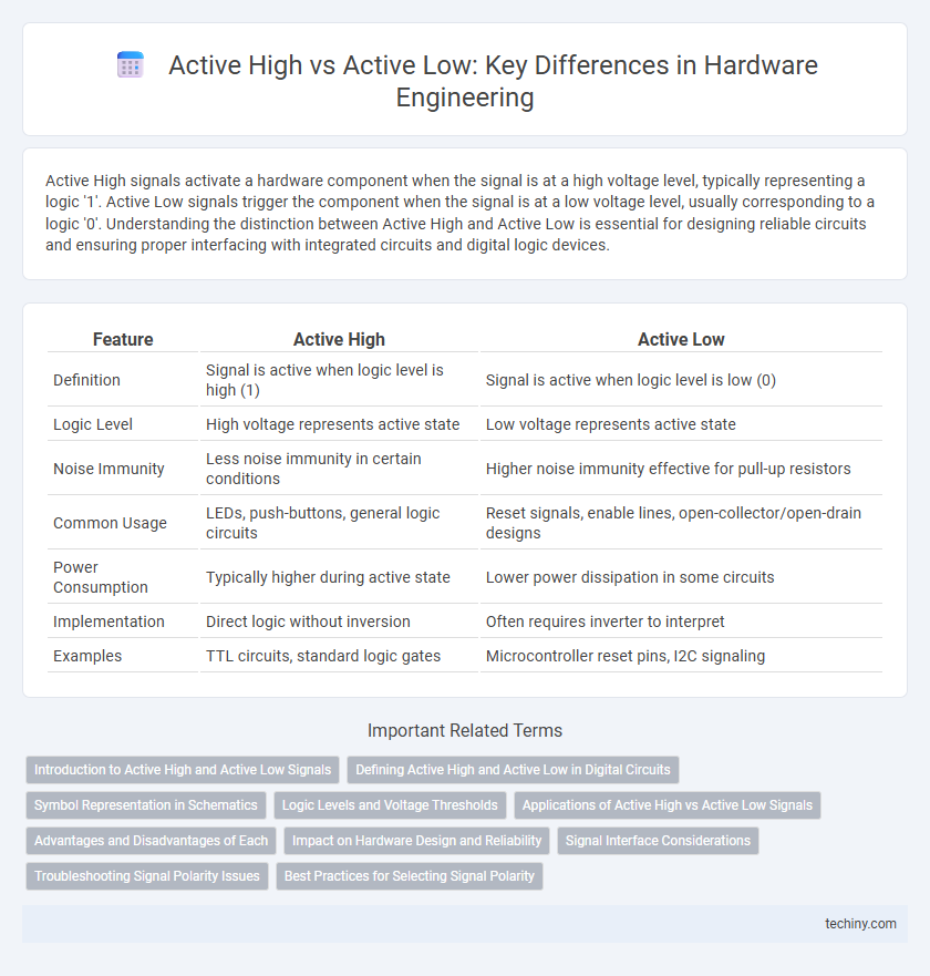
| Feature | Active High | Active Low |
|---|---|---|
| Definition | Signal is active when logic level is high (1) | Signal is active when logic level is low (0) |
| Logic Level | High voltage represents active state | Low voltage represents active state |
| Noise Immunity | Less noise immunity in certain conditions | Higher noise immunity effective for pull-up resistors |
| Common Usage | LEDs, push-buttons, general logic circuits | Reset signals, enable lines, open-collector/open-drain designs |
| Power Consumption | Typically higher during active state | Lower power dissipation in some circuits |
| Implementation | Direct logic without inversion | Often requires inverter to interpret |
| Examples | TTL circuits, standard logic gates | Microcontroller reset pins, I2C signaling |
Introduction to Active High and Active Low Signals
Active High signals are digital signals that activate or enable a device or function when at a logic high level, typically represented by a voltage close to the supply voltage (e.g., 3.3V or 5V). Active Low signals operate inversely, triggering activation when the signal is at a logic low level, near 0V, and are often denoted with a bar or an overline in circuit diagrams. Understanding the distinction between Active High and Active Low signals is crucial for designing and troubleshooting digital circuits, ensuring correct logic interpretation and device operation.
Defining Active High and Active Low in Digital Circuits
Active High signals in digital circuits are defined by a logic level where a high voltage (usually represented as logic 1) activates or enables a device or function. Active Low signals operate inversely, with a low voltage level (logic 0) triggering the activation or operation of the connected component. Understanding the distinction between Active High and Active Low is crucial for designing reliable digital systems and ensuring proper interfacing between integrated circuits.
Symbol Representation in Schematics
Active High signals in hardware schematics are typically represented with standard logic gate symbols without inversion bubbles, indicating the signal is asserted when at a high voltage level. Active Low signals are denoted by an inversion bubble (a small circle) at the input or output of the gate symbol, signaling the signal is asserted when at a low voltage level. This distinction in symbol representation enables clearer interpretation of logic behavior and signal control in circuit designs.
Logic Levels and Voltage Thresholds
Active High logic signals interpret a voltage level close to the supply voltage (typically 3.3V or 5V) as a logical "1," with a voltage threshold often above 2V for CMOS devices. Active Low signals, conversely, recognize a low voltage near ground (0V) as a logical "1," requiring the voltage to fall below a specific threshold, usually around 0.8V. Understanding these voltage thresholds is crucial for designing robust digital circuits, ensuring signal integrity and preventing unintended logic errors in hardware systems.
Applications of Active High vs Active Low Signals
Active High signals are commonly used in microcontroller input buttons and LED indicators, ensuring devices activate when the signal voltage is at a high logic level, optimizing noise immunity. Active Low signals frequently appear in reset circuits and enable lines, where pulling the line low triggers a critical action, providing fail-safe operation during power-up. Understanding the application of Active High versus Active Low signals improves hardware reliability and simplifies circuit design by aligning signal behavior with component requirements.
Advantages and Disadvantages of Each
Active High signals simplify circuit design by directly driving components with a logical high voltage, reducing the need for additional inversion logic and improving signal clarity. Active Low signals offer better noise immunity and lower power consumption in systems where pull-up resistors are preferred, but they can complicate debugging due to inverted logic interpretation. Choosing between Active High and Active Low depends on the specific hardware requirements, such as noise environment, power constraints, and ease of signal tracing in complex designs.
Impact on Hardware Design and Reliability
Active high signals, which trigger circuit responses at a high voltage level, simplify hardware design by reducing noise susceptibility and making signal states more intuitive for debugging. Active low signals, though more prone to noise due to their default high state, enhance reliability by leveraging transistor characteristics that favor sinking current, resulting in lower power consumption and increased robustness against electrical interference. Choosing between active high and active low directly impacts hardware complexity, power efficiency, and overall system reliability in digital circuit design.
Signal Interface Considerations
Active high and active low signaling define the logic level at which a hardware signal interface is considered asserted, with active high signaling asserting a logical '1' voltage level and active low signaling asserting a logical '0' voltage level. Signal interface considerations include noise immunity, power consumption, and compatibility with other components, where active low signals often offer better noise margins due to pull-up resistors and are less susceptible to false triggering. Choosing between active high and active low depends on the specific hardware design requirements, including interfacing logic families and system-level integration constraints.
Troubleshooting Signal Polarity Issues
Troubleshooting signal polarity issues in hardware engineering requires understanding the distinction between active high and active low signals, where active high signals are asserted by a logical high voltage and active low signals are asserted by a logical low voltage. Misinterpreting these signal polarities can lead to circuit malfunction, such as incorrect triggering of components or failure to activate controls. Diagnostic techniques include using oscilloscopes or logic analyzers to verify signal states against expected active levels, ensuring correct logic gate inputs and outputs, and reviewing circuit schematics for proper pull-up or pull-down resistor configurations.
Best Practices for Selecting Signal Polarity
Selecting signal polarity in hardware engineering hinges on minimizing noise susceptibility and ensuring clear logic interpretation; active low signals often excel due to their noise immunity resulting from transistor-level implementations that default to a high state. Best practices include considering the electrical environment, such as electromagnetic interference levels, and the typical logic family voltage thresholds to determine the most reliable signal polarity. Designers should also standardize on active low or active high within a system to simplify debugging and maintain consistent signaling conventions.
Active High vs Active Low Infographic