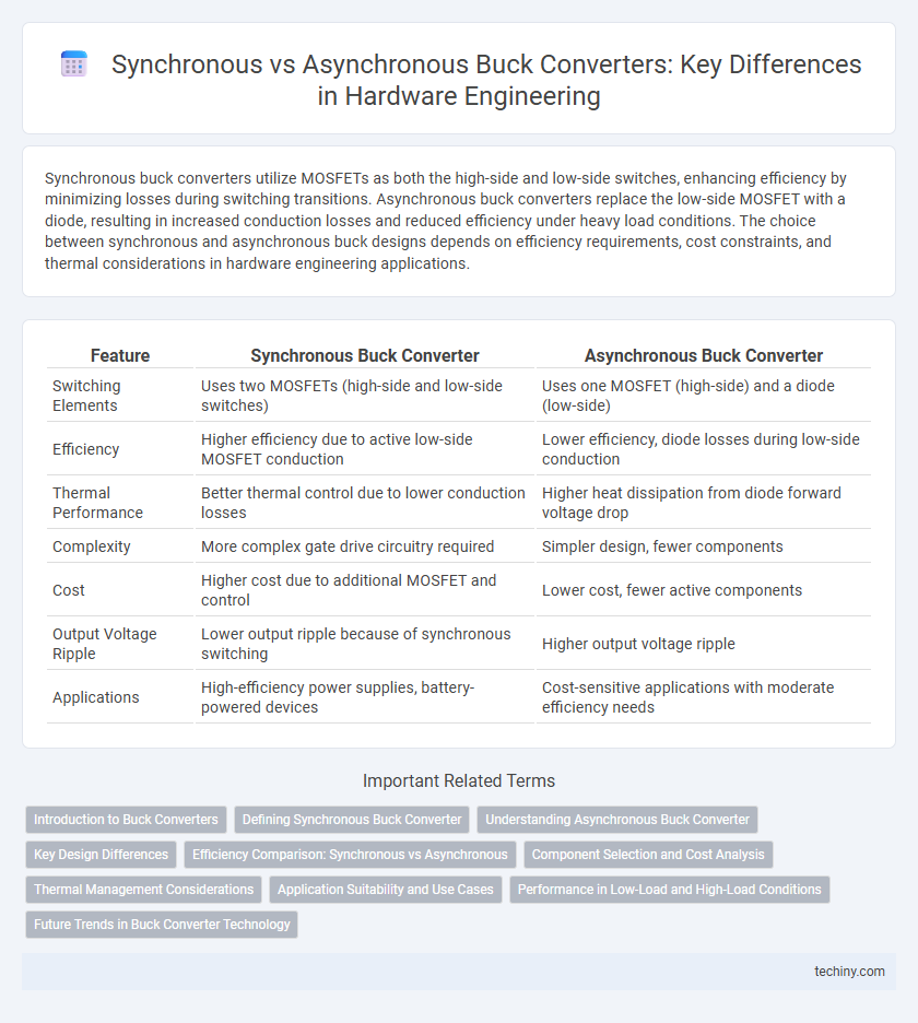
Synchronous buck converters utilize MOSFETs as both the high-side and low-side switches, enhancing efficiency by minimizing losses during switching transitions. Asynchronous buck converters replace the low-side MOSFET with a diode, resulting in increased conduction losses and reduced efficiency under heavy load conditions. The choice between synchronous and asynchronous buck designs depends on efficiency requirements, cost constraints, and thermal considerations in hardware engineering applications.
Table of Comparison
| Feature | Synchronous Buck Converter | Asynchronous Buck Converter |
|---|---|---|
| Switching Elements | Uses two MOSFETs (high-side and low-side switches) | Uses one MOSFET (high-side) and a diode (low-side) |
| Efficiency | Higher efficiency due to active low-side MOSFET conduction | Lower efficiency, diode losses during low-side conduction |
| Thermal Performance | Better thermal control due to lower conduction losses | Higher heat dissipation from diode forward voltage drop |
| Complexity | More complex gate drive circuitry required | Simpler design, fewer components |
| Cost | Higher cost due to additional MOSFET and control | Lower cost, fewer active components |
| Output Voltage Ripple | Lower output ripple because of synchronous switching | Higher output voltage ripple |
| Applications | High-efficiency power supplies, battery-powered devices | Cost-sensitive applications with moderate efficiency needs |
Introduction to Buck Converters
Buck converters are essential DC-DC regulators that step down voltage efficiently in hardware engineering applications. Synchronous buck converters use MOSFETs for both high-side and low-side switches, which improves efficiency and reduces power loss compared to asynchronous buck converters that rely on a diode for the low-side switch. Key performance differences include higher efficiency at low voltages and better thermal management in synchronous designs, making them preferable in modern electronic devices.
Defining Synchronous Buck Converter
A synchronous buck converter uses actively controlled MOSFETs instead of diodes to regulate voltage efficiently, reducing power loss associated with diode voltage drops. This design enhances switching performance and improves overall efficiency, especially at low output voltages and high currents. Synchronous buck converters are widely applied in modern processors and power-sensitive devices requiring stable voltage regulation.
Understanding Asynchronous Buck Converter
An asynchronous buck converter uses a single active switch and a diode for energy transfer, offering a simpler design and lower cost compared to synchronous buck converters, which employ two active switches for improved efficiency. The diode in an asynchronous buck converter conducts during the off-cycle of the main switch, enabling continuous current flow and reducing complexity in control circuitry. Despite slightly lower efficiency and higher power losses due to diode forward voltage drop, asynchronous buck converters are preferred in applications where cost and simplicity outweigh maximum efficiency.
Key Design Differences
Synchronous buck converters integrate a dedicated MOSFET for the low-side switch, enhancing efficiency through reduced conduction losses compared to asynchronous buck converters that use a diode for this role. The synchronous design allows for improved control of switching events, resulting in higher efficiency at light loads and better thermal performance. Asynchronous designs, while simpler and often cheaper, typically incur higher power losses and increased heat dissipation due to the diode's forward voltage drop.
Efficiency Comparison: Synchronous vs Asynchronous
Synchronous buck converters typically achieve higher efficiency than asynchronous buck converters by utilizing MOSFETs for both high-side and low-side switches, which reduces conduction losses significantly. Asynchronous buck converters rely on a diode for the low-side switch, leading to increased power dissipation during the diode's forward voltage drop, especially at higher currents. Consequently, synchronous buck designs are preferred in applications demanding optimal power efficiency and thermal performance.
Component Selection and Cost Analysis
Synchronous buck converters use MOSFETs for both the high-side and low-side switches, improving efficiency and thermal management but requiring more complex and costly components compared to asynchronous buck converters, which utilize a diode for the low-side switch. Component selection in synchronous buck designs demands precise MOSFETs and gate drivers to optimize switching performance, increasing initial cost but reducing conduction losses. Asynchronous buck converters, with simpler component requirements like Schottky diodes, offer lower upfront costs but suffer from higher power dissipation and reduced efficiency, especially at high loads.
Thermal Management Considerations
Synchronous buck converters offer improved thermal management due to lower conduction losses by replacing the diode with a synchronized MOSFET, reducing heat generation and enabling more efficient heat dissipation. In contrast, asynchronous buck converters rely on a diode for the freewheeling path, which increases power loss and results in higher junction temperatures, challenging the thermal design. Effective thermal management in synchronous designs allows for smaller heat sinks and compact PCB layouts, enhancing system reliability and performance in high-current applications.
Application Suitability and Use Cases
Synchronous Buck converters are ideal for applications requiring high efficiency and precise voltage regulation, such as in CPUs, GPUs, and portable devices, due to their use of MOSFETs in both switching elements that minimize power loss. Asynchronous Buck converters suit simpler, cost-sensitive designs like power supplies for LEDs and small embedded systems where efficiency is less critical and design complexity must be minimized, leveraging a diode instead of a synchronous MOSFET. Selection depends on the balance between efficiency needs, thermal performance, complexity, and cost constraints in the target application.
Performance in Low-Load and High-Load Conditions
Synchronous Buck converters deliver higher efficiency than Asynchronous Buck converters at both low-load and high-load conditions due to reduced conduction losses with active low-side MOSFETs. Under low-load scenarios, Synchronous Buck's controlled switching minimizes quiescent current, enhancing energy savings and thermal performance. At high-load conditions, the low R_DS(on) of synchronous MOSFETs ensures superior power handling and reduced heat dissipation compared to diode-based Asynchronous Buck designs.
Future Trends in Buck Converter Technology
Future trends in buck converter technology emphasize the integration of synchronous buck designs due to their superior efficiency and reduced power losses compared to asynchronous buck converters. Innovations in wide-bandgap semiconductors like GaN and SiC enhance switching speeds and thermal performance, driving advancements in synchronous buck converter architectures. Emerging digital control techniques and AI-based optimization further improve dynamic response and energy efficiency in next-generation buck converters.
Synchronous Buck vs Asynchronous Buck Infographic