In hardware engineering, a bus is a shared communication pathway that connects multiple components, enabling data transfer between processors, memory, and peripherals, while a trace refers to the individual conductive paths on a printed circuit board (PCB) that carry electrical signals between components. Buses typically consist of multiple traces bundled together to facilitate parallel data transmission, influencing signal integrity and timing considerations. Designing efficient buses requires careful trace routing, impedance matching, and minimization of crosstalk to ensure reliable hardware performance.
Table of Comparison
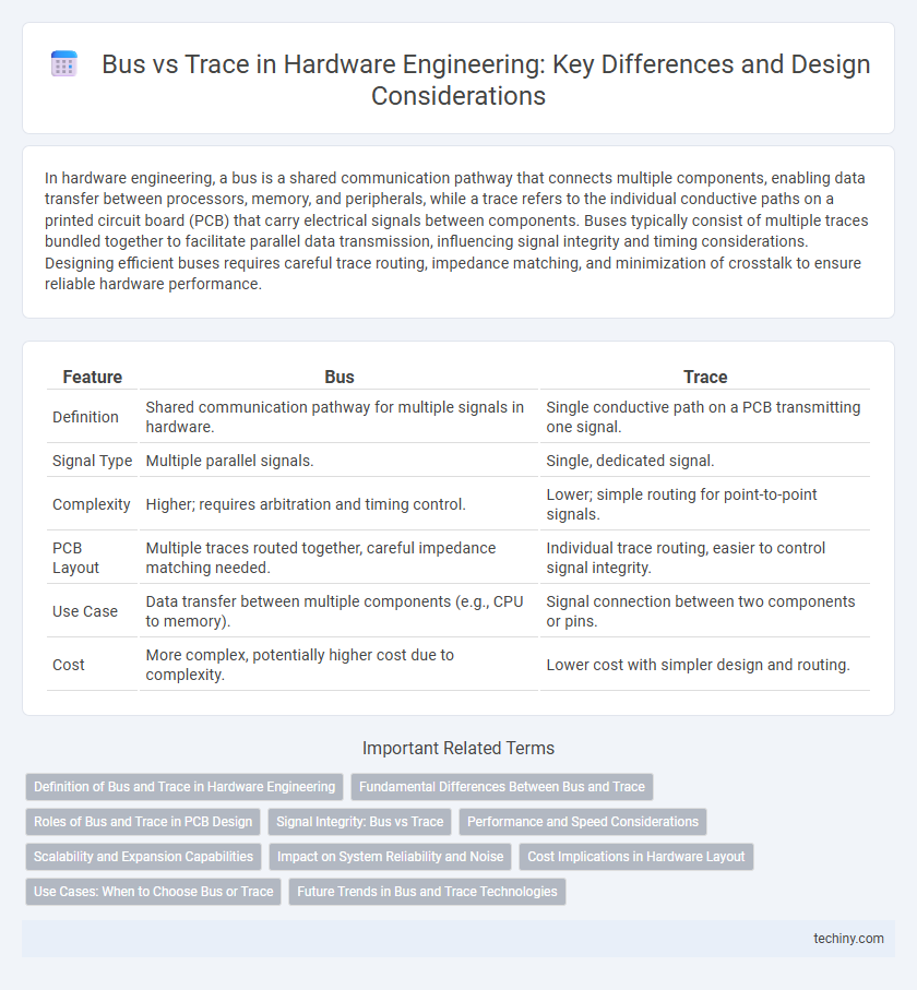
| Feature | Bus | Trace |
|---|---|---|
| Definition | Shared communication pathway for multiple signals in hardware. | Single conductive path on a PCB transmitting one signal. |
| Signal Type | Multiple parallel signals. | Single, dedicated signal. |
| Complexity | Higher; requires arbitration and timing control. | Lower; simple routing for point-to-point signals. |
| PCB Layout | Multiple traces routed together, careful impedance matching needed. | Individual trace routing, easier to control signal integrity. |
| Use Case | Data transfer between multiple components (e.g., CPU to memory). | Signal connection between two components or pins. |
| Cost | More complex, potentially higher cost due to complexity. | Lower cost with simpler design and routing. |
Definition of Bus and Trace in Hardware Engineering
A bus in hardware engineering refers to a set of parallel wires or traces that transmit multiple bits of data simultaneously between components, enabling efficient communication within a computer system. A trace, on the other hand, is a single conductive path on a printed circuit board (PCB) that connects different components, facilitating signal transmission on a granular level. Understanding the distinction between buses and traces is crucial for optimizing data flow, minimizing interference, and designing high-performance PCBs.
Fundamental Differences Between Bus and Trace
A bus in hardware engineering is a communication system that transfers data between components inside a computer or between computers, often consisting of multiple parallel lines or channels facilitating simultaneous transmission of multiple bits. A trace, on the other hand, is a single conductive path on a printed circuit board (PCB) designed to carry electrical signals between components. The fundamental difference lies in their scope and function: buses are complex communication pathways incorporating multiple traces for data transfer, while a trace is a singular connection focused on signal integrity and routing within the PCB.
Roles of Bus and Trace in PCB Design
In PCB design, buses serve as groupings of multiple signal lines that facilitate efficient data transfer between components, enabling organized communication pathways. Traces act as individual conductive routes that physically connect different elements on the board, ensuring precise and reliable signal transmission. Optimizing the roles of buses and traces is crucial for minimizing crosstalk, signal degradation, and maintaining overall signal integrity in complex hardware engineering projects.
Signal Integrity: Bus vs Trace
In hardware engineering, bus and trace configurations critically affect signal integrity, where traces offer direct, low-impedance pathways reducing signal reflection and crosstalk compared to multi-line buses. Buses, consisting of multiple parallel traces, can introduce timing skew and electromagnetic interference, compromising data integrity, especially at high frequencies. Optimizing trace impedance and employing controlled impedance routing techniques enhance signal quality, making dedicated traces preferable in high-speed digital circuit designs for maintaining signal integrity.
Performance and Speed Considerations
Bus architecture in hardware engineering enables parallel data transfer across multiple lines, enhancing throughput and reducing latency for high-speed communication between components. Trace design, involving individual signal paths on a PCB, is optimized for minimal signal degradation and impedance control, directly impacting signal integrity and speed. Superior performance depends on balancing bus width and trace length with impedance matching to minimize crosstalk, delay, and signal distortion in high-frequency circuits.
Scalability and Expansion Capabilities
Bus architectures offer scalability by enabling modular expansion through standardized connectors and protocols, supporting multiple devices on a shared communication path. Trace design emphasizes physical routing on PCBs, where scalability depends on signal integrity and trace length constraints, impacting expansion potential. Efficient bus systems facilitate easier integration of additional components, while trace-based limitations require careful planning to maintain performance with system growth.
Impact on System Reliability and Noise
Bus architectures improve system reliability by providing defined communication pathways that reduce signal interference, while complex bus designs can increase noise susceptibility if not properly shielded. Trace layouts on PCBs influence noise levels through their length, width, and routing, where shorter, well-routed traces minimize crosstalk and electromagnetic interference (EMI). Ensuring optimal bus configurations and precise trace design is critical for maintaining signal integrity and enhancing overall hardware system robustness.
Cost Implications in Hardware Layout
Bus architectures in hardware layout often incur higher costs due to the increased complexity of routing multiple signals simultaneously, necessitating more PCB layers and precise impedance control. In contrast, single trace layouts reduce material usage and manufacturing complexity, leading to lower production expenses but may limit data throughput. Optimizing between bus and trace designs requires balancing signal integrity needs with budget constraints to achieve cost-effective hardware engineering solutions.
Use Cases: When to Choose Bus or Trace
Choose a bus architecture when multiple components require shared communication paths with synchronized data transfer, typical in complex systems like microcontrollers or FPGA designs. Opt for trace routing in high-speed signal applications where controlled impedance and minimal crosstalk are critical, such as in PCB layout for processor-memory connections. Buses offer scalability and ease of expansion, whereas traces provide optimized performance for point-to-point communication.
Future Trends in Bus and Trace Technologies
Future trends in bus and trace technologies emphasize increased data transfer speeds and enhanced signal integrity to meet the demands of high-performance hardware engineering. Advanced materials like graphene and innovations in optical bus systems are driving reductions in latency and power consumption. Integration of AI-driven diagnostics and adaptive routing algorithms is expected to optimize trace layouts, boosting reliability and efficiency in complex circuit designs.
Bus vs Trace Infographic