Pulse Width Modulation (PWM) controls analog circuits by varying the duty cycle of a digital signal, offering cost-effective and efficient power management in hardware engineering. Digital-to-Analog Converters (DACs) provide precise voltage output by converting digital values into continuous analog signals, ideal for applications requiring high accuracy and linearity. Choosing between PWM and DAC depends on the required signal resolution, power efficiency, and design complexity in embedded systems.
Table of Comparison
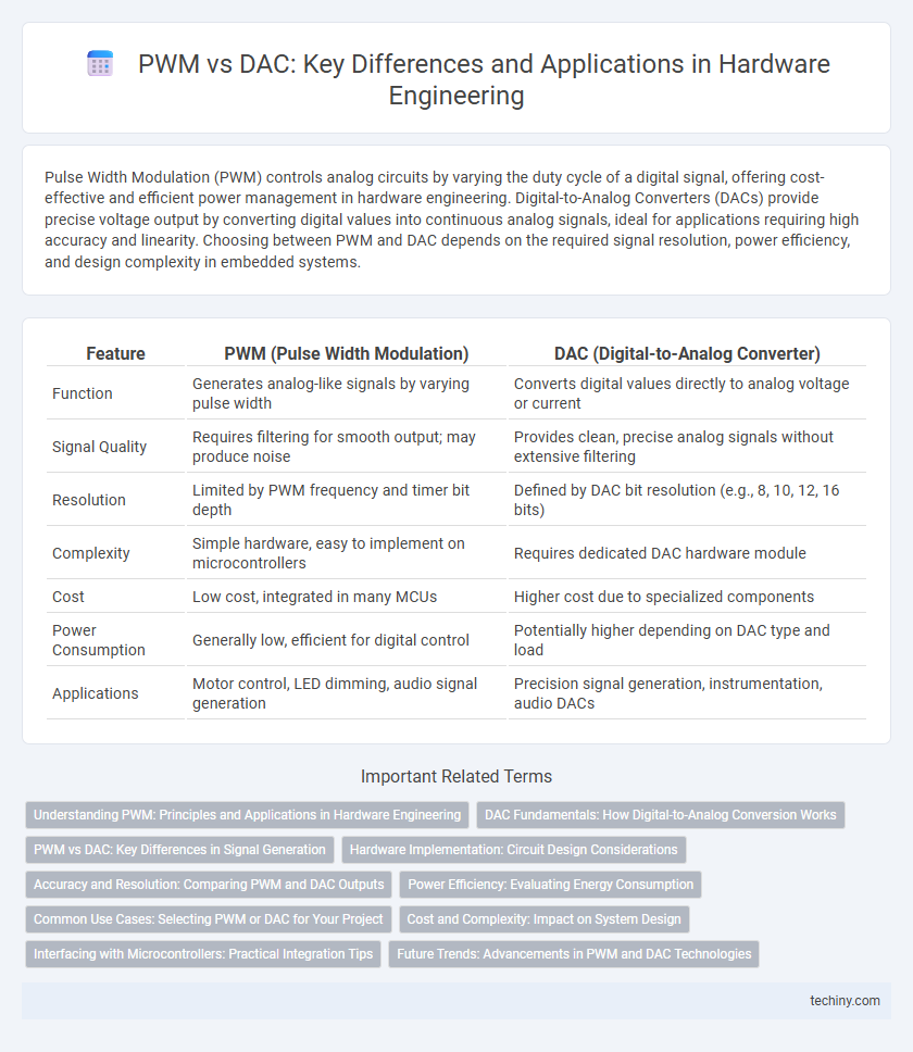
| Feature | PWM (Pulse Width Modulation) | DAC (Digital-to-Analog Converter) |
|---|---|---|
| Function | Generates analog-like signals by varying pulse width | Converts digital values directly to analog voltage or current |
| Signal Quality | Requires filtering for smooth output; may produce noise | Provides clean, precise analog signals without extensive filtering |
| Resolution | Limited by PWM frequency and timer bit depth | Defined by DAC bit resolution (e.g., 8, 10, 12, 16 bits) |
| Complexity | Simple hardware, easy to implement on microcontrollers | Requires dedicated DAC hardware module |
| Cost | Low cost, integrated in many MCUs | Higher cost due to specialized components |
| Power Consumption | Generally low, efficient for digital control | Potentially higher depending on DAC type and load |
| Applications | Motor control, LED dimming, audio signal generation | Precision signal generation, instrumentation, audio DACs |
Understanding PWM: Principles and Applications in Hardware Engineering
Pulse Width Modulation (PWM) controls the power delivered to electrical devices by varying the duty cycle of a digital signal, effectively simulating analog voltage levels. PWM is widely applied in hardware engineering for motor speed control, LED dimming, and power regulation due to its efficiency and simplicity compared to Digital-to-Analog Converters (DACs). Unlike DACs, which provide continuous voltage outputs, PWM achieves similar control through rapid switching, minimizing hardware complexity and cost.
DAC Fundamentals: How Digital-to-Analog Conversion Works
Digital-to-Analog Conversion (DAC) transforms binary digital signals into continuous analog voltages by converting discrete digital codes into proportional analog output levels through precise resistor ladders or current steering architectures. This process relies on quantization steps defined by the DAC's resolution, typically measured in bits, which determines the output voltage's granularity and accuracy. The continuous analog signal output from a DAC enables seamless interfacing with real-world hardware components requiring smooth voltage variations, contrasting with the pulsed outputs generated by Pulse Width Modulation (PWM) systems.
PWM vs DAC: Key Differences in Signal Generation
PWM (Pulse Width Modulation) generates signals by switching between on and off states at a fixed frequency, modulating the duty cycle to represent analog values efficiently in hardware control applications. DAC (Digital-to-Analog Converter) produces continuous analog voltage levels directly from digital input codes, offering higher resolution and smoother output suitable for audio and precise instrumentation. The fundamental difference lies in PWM's digital pulse train approximation versus DAC's direct voltage synthesis, impacting accuracy, complexity, and power consumption in signal generation.
Hardware Implementation: Circuit Design Considerations
Pulse Width Modulation (PWM) circuits typically require fewer components, using digital switches like MOSFETs and a timer or microcontroller for signal generation, making them more power-efficient and easier to implement in embedded systems. Digital-to-Analog Converters (DACs) rely on resistor ladders, current steering networks, or sigma-delta modulators, which demand precise component matching and layout considerations to minimize linearity and noise issues. Designing PWM circuits focuses on filtering and switching speed optimization, whereas DAC implementations prioritize accuracy, thermal stability, and minimizing integral and differential nonlinearity.
Accuracy and Resolution: Comparing PWM and DAC Outputs
PWM (Pulse Width Modulation) outputs offer limited resolution based on the timer's bit depth, typically ranging from 8 to 16 bits, which can introduce quantization noise in analog signal representation. DACs (Digital-to-Analog Converters) provide higher accuracy and finer resolution, often exceeding 12 to 24 bits, enabling smoother and more precise voltage outputs crucial for sensitive hardware applications. Precision hardware engineering tasks often require DACs for their stable, high-fidelity analog signals, while PWM is preferred for cost-effective digital control where moderate accuracy suffices.
Power Efficiency: Evaluating Energy Consumption
PWM (Pulse Width Modulation) circuits typically consume less power than DACs (Digital-to-Analog Converters) because they switch between full on and off states, minimizing energy dissipation. DACs generate continuous voltage levels, often resulting in higher static power consumption due to analog components like resistors and amplifiers. Evaluating energy consumption, PWM proves more power-efficient for applications requiring variable control signals without precise analog output fidelity.
Common Use Cases: Selecting PWM or DAC for Your Project
PWM excels in motor control and LED dimming due to its efficient power management and ease of implementation in embedded systems. DAC is preferred for audio output and precision signal generation where accurate voltage levels are critical. Choosing between PWM and DAC depends on whether the project prioritizes efficient digital control or precise analog signal reproduction.
Cost and Complexity: Impact on System Design
PWM controllers offer a cost-effective and simpler hardware solution compared to DACs, as they require fewer components and straightforward circuitry. DACs, while providing higher precision and smoother analog output, increase system complexity due to their need for additional filtering, reference voltage sources, and more sophisticated control logic. The choice between PWM and DAC directly affects overall system cost, design complexity, and power consumption in hardware engineering.
Interfacing with Microcontrollers: Practical Integration Tips
PWM signals are commonly used for interfacing with microcontrollers due to their simplicity and ease of generation using built-in timers, enabling efficient control over actuators and LEDs. DAC outputs provide true analog voltage levels, ideal for precision applications but often require external components or microcontrollers with integrated DAC modules. When integrating, consider PWM filtering with RC circuits for smoother analog output, while DACs need careful power supply and grounding to minimize noise and ensure signal integrity.
Future Trends: Advancements in PWM and DAC Technologies
Future trends in hardware engineering reveal significant advancements in Pulse Width Modulation (PWM) and Digital-to-Analog Converter (DAC) technologies, enhancing precision and efficiency in signal processing. Emerging high-resolution PWM controllers offer improved power management for electric vehicles and renewable energy systems, while next-generation DACs deliver ultra-low latency and higher sampling rates for audio and communication applications. Integration of AI-driven algorithms with PWM and DAC circuits promises dynamic adaptability and optimized performance in IoT and industrial automation sectors.
PWM vs DAC Infographic