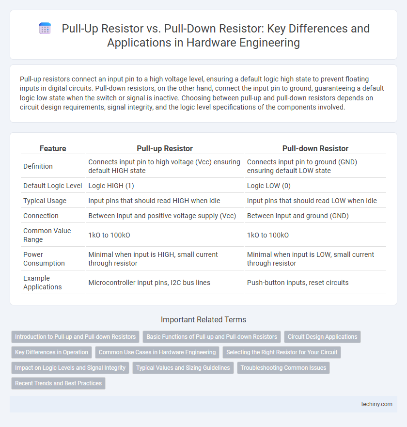
Pull-up resistors connect an input pin to a high voltage level, ensuring a default logic high state to prevent floating inputs in digital circuits. Pull-down resistors, on the other hand, connect the input pin to ground, guaranteeing a default logic low state when the switch or signal is inactive. Choosing between pull-up and pull-down resistors depends on circuit design requirements, signal integrity, and the logic level specifications of the components involved.
Table of Comparison
| Feature | Pull-up Resistor | Pull-down Resistor |
|---|---|---|
| Definition | Connects input pin to high voltage (Vcc) ensuring default HIGH state | Connects input pin to ground (GND) ensuring default LOW state |
| Default Logic Level | Logic HIGH (1) | Logic LOW (0) |
| Typical Usage | Input pins that should read HIGH when idle | Input pins that should read LOW when idle |
| Connection | Between input and positive voltage supply (Vcc) | Between input and ground (GND) |
| Common Value Range | 1kO to 100kO | 1kO to 100kO |
| Power Consumption | Minimal when input is HIGH, small current through resistor | Minimal when input is LOW, small current through resistor |
| Example Applications | Microcontroller input pins, I2C bus lines | Push-button inputs, reset circuits |
Introduction to Pull-up and Pull-down Resistors
Pull-up and pull-down resistors are essential components in hardware engineering used to ensure a known logic level on a digital input pin when no active device is connected. A pull-up resistor connects the input to a high voltage level (usually Vcc), preventing the input from floating and reading undefined states. Conversely, a pull-down resistor connects the input to ground (GND), establishing a default low logic level and stabilizing the input signal.
Basic Functions of Pull-up and Pull-down Resistors
Pull-up resistors ensure a default high voltage level by connecting the input to the power supply, preventing floating states and stabilizing digital signals. Pull-down resistors maintain a default low voltage level by connecting the input to ground, ensuring reliable logic low readings. Both resistors improve signal integrity and prevent undefined input conditions in digital circuits.
Circuit Design Applications
Pull-up resistors connect a voltage supply to a signal line to ensure a default HIGH state, preventing floating inputs and noise in digital circuits. Pull-down resistors tie the signal line to ground, securing a default LOW state, which is crucial in switches and microcontroller inputs to avoid undefined behavior. In circuit design, selecting between pull-up and pull-down resistors depends on the logic level requirements, power consumption considerations, and the specific input characteristics of integrated circuits.
Key Differences in Operation
Pull-up resistors connect a signal line to a positive voltage supply, ensuring the line reads a high logic level when not actively driven, while pull-down resistors connect the line to ground, maintaining a low logic level in idle state. Pull-up resistors prevent floating inputs by sourcing current, whereas pull-down resistors sink current to stabilize input voltages. The choice between pull-up and pull-down resistors depends on the desired default logic state and circuit design requirements.
Common Use Cases in Hardware Engineering
Pull-up resistors are commonly used to ensure a defined high logic level on input pins in digital circuits, preventing floating states and false triggering. Pull-down resistors serve to maintain a defined low logic level, especially in switches and buttons connected to microcontroller inputs. Both types are essential for stable signal conditioning in hardware designs involving microprocessors and logic gates.
Selecting the Right Resistor for Your Circuit
Selecting the right resistor for your circuit requires understanding the function of pull-up and pull-down resistors in establishing defined voltage levels. Pull-up resistors connect input pins to the positive voltage supply, ensuring a default HIGH state, while pull-down resistors connect to ground to guarantee a default LOW state. Factors such as resistor value, power consumption, and the specific logic level requirements of your microcontroller or IC determine the optimal choice between pull-up and pull-down configurations.
Impact on Logic Levels and Signal Integrity
Pull-up resistors maintain a default high logic level by connecting the signal line to a positive voltage, minimizing noise susceptibility and ensuring stable voltage levels in open-drain or open-collector circuits. Pull-down resistors secure a default low logic level by linking the signal line to ground, preventing floating states that can cause unpredictable logic behavior and signal integrity issues. Proper selection and placement of pull-up or pull-down resistors are critical for reducing signal reflections, avoiding false triggering, and optimizing reliable digital circuit performance.
Typical Values and Sizing Guidelines
Pull-up resistors typically range from 1 kO to 10 kO to ensure reliable high-level voltage detection while minimizing power consumption, whereas pull-down resistors are often sized similarly but can vary based on the input characteristics of the connected device. Choosing resistor values involves balancing current draw and noise immunity; lower resistance improves noise tolerance but increases power usage, while higher resistance reduces current but may cause voltage fluctuations. Guidelines recommend starting with 4.7 kO for general-purpose circuits and adjusting based on specific IC input thresholds and bus capacitance to optimize signal integrity.
Troubleshooting Common Issues
Pull-up and pull-down resistors often cause issues such as floating inputs and improper logic level detection, leading to erratic circuit behavior. Troubleshooting involves verifying resistor values and ensuring proper connection to the correct voltage rail; pull-up resistors connect to VCC while pull-down resistors connect to GND. Using a multimeter to check voltage levels at the input pins can quickly identify if the resistor is functioning correctly or if a misplaced or faulty resistor is causing logic state problems.
Recent Trends and Best Practices
Pull-up and pull-down resistors remain essential in hardware engineering for ensuring defined logic levels and preventing floating inputs in digital circuits. Recent trends emphasize minimizing power consumption by selecting resistor values that balance speed and current draw, with 10kO being a common standard, while newer designs incorporate integrated resistors to reduce PCB complexity and improve reliability. Best practices include carefully analyzing input pin characteristics and signal integrity needs, applying simulation tools for optimized resistor placement, and leveraging low-leakage CMOS technologies to enhance noise immunity and reduce power loss.
Pull-up resistor vs Pull-down resistor Infographic