Pin headers consist of a row of male pins designed to fit into corresponding female connectors, making them ideal for permanent or semi-permanent circuit connections. Socket headers, featuring female contacts, allow easy insertion and removal of pin headers, providing flexibility for modular hardware designs. Choosing between pin and socket headers depends on the need for durability versus reusability in electronic device assembly.
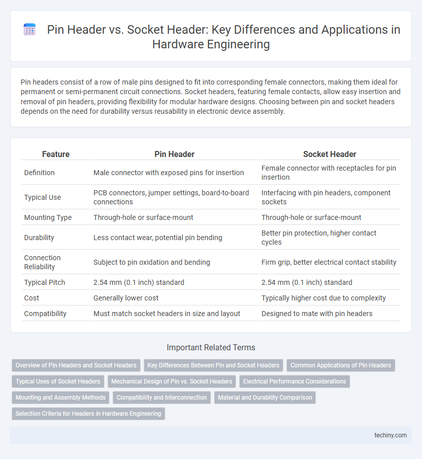
Table of Comparison
| Feature | Pin Header | Socket Header |
|---|---|---|
| Definition | Male connector with exposed pins for insertion | Female connector with receptacles for pin insertion |
| Typical Use | PCB connectors, jumper settings, board-to-board connections | Interfacing with pin headers, component sockets |
| Mounting Type | Through-hole or surface-mount | Through-hole or surface-mount |
| Durability | Less contact wear, potential pin bending | Better pin protection, higher contact cycles |
| Connection Reliability | Subject to pin oxidation and bending | Firm grip, better electrical contact stability |
| Typical Pitch | 2.54 mm (0.1 inch) standard | 2.54 mm (0.1 inch) standard |
| Cost | Generally lower cost | Typically higher cost due to complexity |
| Compatibility | Must match socket headers in size and layout | Designed to mate with pin headers |
Overview of Pin Headers and Socket Headers
Pin headers consist of a row or grid of metal pins protruding from a plastic base, designed for insertion into through-hole or surface-mount PCB pads. Socket headers feature corresponding receptacles that provide a secure, removable connection for pin headers, facilitating easy assembly and maintenance. Both components are critical in hardware engineering for modular circuit design, enabling reliable electrical connections and flexibility in prototyping and product development.
Key Differences Between Pin and Socket Headers
Pin headers consist of male pins that protrude from a connector, designed for insertion into socket headers, which contain female contacts to securely connect printed circuit boards (PCBs) or cables. Pin headers provide a robust mechanical connection, making them ideal for permanent or semi-permanent installations, while socket headers offer flexibility for easy disconnection and reconnection, facilitating maintenance and upgrades. The key differences include their physical design, electrical contact reliability, mating cycles, and application suitability within hardware engineering environments.
Common Applications of Pin Headers
Pin headers are widely used in hardware engineering for establishing reliable connections on printed circuit boards (PCBs), especially in prototyping and modular electronics. They facilitate easy and quick connection of wires, components, or jumper cables in applications like microcontroller boards, sensors, and expansion modules. Their compatibility with various connectors and ease of soldering make them suitable for custom circuit designs and embedded systems.
Typical Uses of Socket Headers
Socket headers are typically used in hardware engineering to provide flexible, removable connections between components such as printed circuit boards (PCBs) and modules or integrated circuits (ICs). They facilitate easy replacement, upgrades, and repairs by allowing ICs or daughter boards to be plugged and unplugged without soldering, making them ideal for prototyping and modular designs. Common applications include microcontroller programming, sensor interfaces, and connecting external peripherals where frequent disassembly is necessary.
Mechanical Design of Pin vs. Socket Headers
Pin headers feature rigid metal pins arranged in a single or double row, designed for direct insertion into PCB holes, providing firm mechanical stability and reliable electrical contact. Socket headers incorporate spring-loaded contacts within a plastic housing, enabling flexible engagement with pins and accommodating slight misalignment or vibration without compromising connection integrity. Mechanical design considerations for pin versus socket headers revolve around durability, tolerance for repeated mating cycles, and resistance to mechanical stress in connectors used in embedded systems or industrial hardware.
Electrical Performance Considerations
Pin headers typically offer lower contact resistance due to their fixed metal pins, ensuring stable electrical connections with minimal signal loss. Socket headers provide greater flexibility and ease of replacement but may introduce higher contact resistance and potential signal degradation, especially in high-frequency applications. Selecting between pin and socket headers depends on balancing electrical performance requirements with mechanical durability and maintenance needs.
Mounting and Assembly Methods
Pin headers are typically through-hole mounted on PCBs, providing secure mechanical connections by soldering pins through drilled holes, which enhances durability in harsh environments. Socket headers are often surface-mounted, allowing easy insertion and removal of mating connectors, facilitating modular assembly and maintenance. Both types require precise alignment during assembly to ensure reliable electrical contacts and mechanical stability in hardware engineering applications.
Compatibility and Interconnection
Pin headers and socket headers are complementary components widely used in hardware engineering for board-to-board and board-to-wire connections. Pin headers consist of rigid metal pins that plug directly into socket headers, which contain corresponding receptacles designed for secure electrical contact and mechanical stability. Ensuring compatibility between pitch size, row configuration, and pin count is critical for seamless interconnection and reliable signal transmission in electronic assemblies.
Material and Durability Comparison
Pin headers are typically crafted from brass or phosphor bronze with a tin or gold plating, offering excellent conductivity and corrosion resistance for long-lasting electrical performance. Socket headers often use similar base metals but incorporate additional plastic housings like PBT or Nylon, enhancing mechanical stability and thermal resistance under repeated mating cycles. While pin headers provide robust contact integrity, socket headers excel in durability due to reinforced insulation materials and secure locking mechanisms, making them ideal for frequent connect-disconnect applications.
Selection Criteria for Headers in Hardware Engineering
Selection criteria for pin headers versus socket headers in hardware engineering emphasize compatibility, electrical performance, and mechanical stability. Pin headers are preferred for permanent soldered connections due to their robust mechanical strength and excellent conductivity, while socket headers are ideal for modular designs requiring easy insertion and removal of components. Engineers prioritize pitch size, current rating, and mating cycles to ensure reliable signal integrity and longevity in various electronic applications.
Pin header vs Socket header Infographic