SMD resistors offer compact size and enhanced performance for high-density circuit designs, making them ideal for modern electronic devices requiring miniaturization. PTH resistors provide robust mechanical strength and ease of replacement, suitable for applications where durability and higher power ratings are critical. Choosing between SMD and PTH resistors depends on the specific requirements of space, power handling, and assembly process in hardware engineering projects.
Table of Comparison
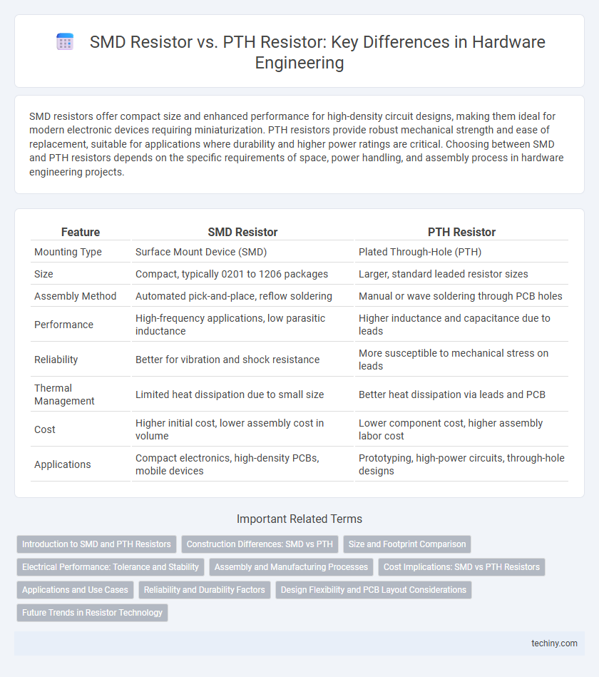
| Feature | SMD Resistor | PTH Resistor |
|---|---|---|
| Mounting Type | Surface Mount Device (SMD) | Plated Through-Hole (PTH) |
| Size | Compact, typically 0201 to 1206 packages | Larger, standard leaded resistor sizes |
| Assembly Method | Automated pick-and-place, reflow soldering | Manual or wave soldering through PCB holes |
| Performance | High-frequency applications, low parasitic inductance | Higher inductance and capacitance due to leads |
| Reliability | Better for vibration and shock resistance | More susceptible to mechanical stress on leads |
| Thermal Management | Limited heat dissipation due to small size | Better heat dissipation via leads and PCB |
| Cost | Higher initial cost, lower assembly cost in volume | Lower component cost, higher assembly labor cost |
| Applications | Compact electronics, high-density PCBs, mobile devices | Prototyping, high-power circuits, through-hole designs |
Introduction to SMD and PTH Resistors
SMD resistors, or Surface-Mount Device resistors, are compact components designed for automated placement on printed circuit boards (PCBs), offering high-density assembly and superior performance in high-frequency applications. PTH resistors, or Plated Through-Hole resistors, feature leads that pass through PCB holes for soldering, providing robust mechanical connections ideal for high-stress or high-power environments. Understanding the distinctions between SMD and PTH resistors is crucial for selecting the appropriate resistor type based on space constraints, assembly methods, and electrical requirements in hardware engineering.
Construction Differences: SMD vs PTH
SMD resistors feature a compact, rectangular ceramic substrate with metal terminations on each end, designed for surface mounting directly onto PCB pads, enabling high-density circuit layouts and automated assembly. In contrast, PTH resistors consist of a cylindrical resistor body with wire leads extending from both ends, requiring insertion into drilled holes on the PCB and soldering on the opposite side, which results in a more robust mechanical connection but occupies more space. The construction differences significantly impact assembly efficiency, thermal performance, and application suitability in modern electronic devices.
Size and Footprint Comparison
SMD resistors typically have a significantly smaller size and footprint compared to PTH resistors, making them ideal for compact PCB designs in modern electronics. The surface-mount technology allows SMD resistors to be placed directly on the PCB surface, reducing the overall board area and enabling higher component density. In contrast, PTH resistors require holes through the PCB, leading to larger footprints and increased assembly complexity.
Electrical Performance: Tolerance and Stability
SMD resistors typically offer tighter tolerance levels, often as low as +-0.1%, which enhances precision in electrical circuits compared to PTH resistors that generally have tolerances around +-1% or higher. The stability of SMD resistors under thermal and mechanical stress is superior due to their smaller size and surface mounting technology, reducing drift in resistance values over time. In contrast, PTH resistors, while robust for high-power applications, exhibit greater resistance variability and less consistent tolerance when exposed to environmental changes.
Assembly and Manufacturing Processes
SMD resistors enable automated pick-and-place assembly, significantly increasing production speed and reducing labor costs compared to PTH resistors that require manual insertion and wave soldering. The surface-mount technology (SMT) process used for SMD resistors offers higher component density and improved reliability in mass manufacturing. PTH resistors involve through-hole drilling and soldering, which increases manufacturing time and complexity but can provide stronger mechanical bonds for high-stress applications.
Cost Implications: SMD vs PTH Resistors
Surface Mount Device (SMD) resistors often present a lower overall cost in high-volume production due to automated assembly processes and reduced labor requirements compared to Plated Through Hole (PTH) resistors. PTH resistors typically incur higher costs from manual or wave soldering and increased material usage associated with larger component sizes and drilling holes in PCBs. Cost implications also stem from PCB manufacturing complexity, where SMD designs allow for more compact layouts, reducing board size and material expenses.
Applications and Use Cases
SMD resistors are ideal for high-density PCB designs, such as smartphones and wearables, due to their compact size and automated assembly compatibility. PTH resistors are preferred in applications requiring higher power dissipation and mechanical stability, typically found in industrial equipment and power supplies. Each type offers distinct advantages depending on space constraints, power requirements, and manufacturing processes.
Reliability and Durability Factors
SMD resistors offer superior reliability due to their smaller size and reduced lead inductance, minimizing failure points in high-vibration environments compared to PTH resistors. PTH resistors, while easier to replace, present increased mechanical stress on solder joints leading to potential failures under thermal cycling and shock. Durability of SMD resistors is enhanced by their low profile and secure surface mounting, which better withstands environmental factors like moisture and mechanical wear.
Design Flexibility and PCB Layout Considerations
SMD resistors offer superior design flexibility due to their compact size, enabling higher component density on PCBs and facilitating complex circuit layouts with reduced parasitic inductance and capacitance. PTH resistors, while larger, provide robust mechanical strength and ease of manual assembly, making them suitable for applications requiring frequent handling or higher power dissipation. PCB layout considerations prioritize SMD components for automated production and miniaturization, whereas PTH resistors are preferred in designs that accommodate through-hole mounting and require enhanced durability.
Future Trends in Resistor Technology
SMD resistors dominate modern hardware engineering due to their compact size and compatibility with automated assembly, driving ongoing miniaturization in electronic designs. Future trends emphasize the development of ultra-thin, high-precision SMD resistors with enhanced thermal stability and lower parasitic inductance to meet the demands of high-frequency applications. Innovations in materials science and nanotechnology are poised to further improve resistor performance and integration, potentially redefining standard PTH resistor usage in next-generation electronic devices.
SMD Resistor vs PTH Resistor Infographic