Surface mount devices (SMD) offer a compact design and higher component density compared to through-hole technology, making them ideal for modern electronics with space constraints. Through-hole components provide superior mechanical strength and are preferred for applications requiring durability and easier prototyping or manual assembly. Choosing between SMD and through-hole depends on factors such as manufacturing volume, circuit complexity, and mechanical stability requirements.
Table of Comparison
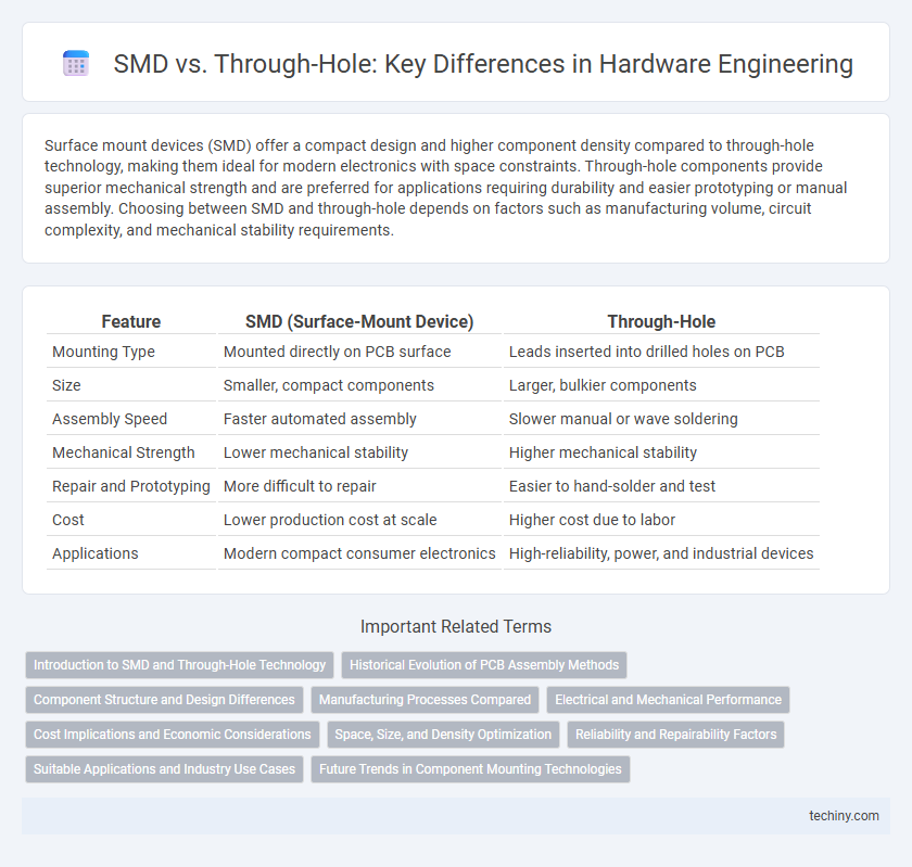
| Feature | SMD (Surface-Mount Device) | Through-Hole |
|---|---|---|
| Mounting Type | Mounted directly on PCB surface | Leads inserted into drilled holes on PCB |
| Size | Smaller, compact components | Larger, bulkier components |
| Assembly Speed | Faster automated assembly | Slower manual or wave soldering |
| Mechanical Strength | Lower mechanical stability | Higher mechanical stability |
| Repair and Prototyping | More difficult to repair | Easier to hand-solder and test |
| Cost | Lower production cost at scale | Higher cost due to labor |
| Applications | Modern compact consumer electronics | High-reliability, power, and industrial devices |
Introduction to SMD and Through-Hole Technology
Surface Mount Device (SMD) technology allows electronic components to be mounted directly onto the surface of printed circuit boards (PCBs), enabling smaller, lighter designs and automated assembly processes. Through-hole technology involves inserting component leads through pre-drilled holes on a PCB, providing stronger mechanical bonds and better performance for high-stress environments. Both methods are integral to hardware engineering, with SMD favored for compact, high-density circuits and through-hole preferred for durability and prototyping.
Historical Evolution of PCB Assembly Methods
Surface-mount technology (SMT) revolutionized PCB assembly by enabling smaller, more complex circuits compared to traditional through-hole methods, which dominated early electronics due to their mechanical strength and ease of manual soldering. The transition from through-hole to SMD began in the 1980s, driven by the demand for miniaturization and higher circuit density in consumer electronics and computing devices. Modern manufacturing now favors SMD for automated assembly, improved performance, and cost efficiency, marking a significant evolution in hardware engineering practices.
Component Structure and Design Differences
Surface-mount devices (SMD) feature a compact, flat design with short leads or no leads, allowing direct placement on PCB pads, while through-hole components have long leads designed to pass through holes on the PCB for soldering. SMD components enable higher component density and reduced parasitic inductance due to their smaller size and proximity to the PCB surface. Through-hole components provide stronger mechanical bonds suitable for high-stress applications but occupy more board space and often result in more complex PCB layouts.
Manufacturing Processes Compared
Surface Mount Device (SMD) technology enables automated, high-speed placement on circuit boards, significantly reducing labor costs and increasing production efficiency compared to through-hole components, which require manual insertion and wave soldering. SMD parts facilitate higher component density and smaller board sizes, optimizing space and signal integrity for modern electronics. Through-hole mounting offers superior mechanical strength and durability, making it preferable for high-stress industrial applications despite longer assembly time and increased manufacturing complexity.
Electrical and Mechanical Performance
Surface Mount Devices (SMD) offer superior electrical performance due to shorter lead lengths and reduced parasitic inductance and capacitance, enhancing signal integrity in high-frequency applications. Through-hole components provide robust mechanical strength by anchoring leads through the PCB, making them ideal for applications subject to mechanical stress or high vibration. SMDs enable higher component density and automated assembly, while through-hole components excel in durability and reliable mechanical connections.
Cost Implications and Economic Considerations
Surface-mount devices (SMD) reduce manufacturing costs through automated assembly and smaller component sizes, enabling higher production speed and lower labor expenses compared to through-hole technology. Through-hole components incur higher costs due to manual insertion, greater material usage, and increased board space requirements, which elevate overall production and material expenses. Economic considerations favor SMD for large-scale manufacturing, while through-hole remains cost-effective for prototyping and low-volume, high-reliability applications.
Space, Size, and Density Optimization
SMD components enable higher circuit density with minimal board space due to their compact, flat design that mounts directly onto the PCB surface. Through-hole technology requires larger holes and more space on the PCB, limiting component density and increasing overall board size. Optimizing for space and size, SMD is preferred in modern hardware engineering where miniaturization and high-density layouts are critical.
Reliability and Repairability Factors
Surface-mount devices (SMD) offer higher reliability due to shorter lead lengths and reduced mechanical stress, minimizing solder joint defects in hardware engineering. Through-hole components provide superior repairability because their leads extend through the PCB, allowing easier manual replacement and stronger mechanical connections under thermal or vibration stress. Selecting between SMD and through-hole depends on balancing long-term reliability requirements with the necessity for straightforward maintenance and repair access.
Suitable Applications and Industry Use Cases
Surface-mount devices (SMD) are ideal for high-density, compact electronics such as smartphones, laptops, and wearable devices, enabling automated assembly and cost-efficient mass production. Through-hole components offer superior mechanical strength and reliability, making them preferred for industrial equipment, automotive electronics, and aerospace applications requiring robust connections under harsh conditions. Both technologies are integral to hardware engineering, selected based on factors like environmental stress, assembly complexity, and product lifespan.
Future Trends in Component Mounting Technologies
Surface Mount Device (SMD) technology continues to dominate hardware engineering due to its compatibility with automated assembly and higher component density, enhancing miniaturization and performance in modern electronics. Future trends highlight advanced SMD packaging innovations such as embedded components and 3D integration, which improve heat dissipation and electrical characteristics. Through-hole technology still retains niche applications requiring enhanced mechanical strength and reliability, but progressive hybrid mounting techniques are expected to merge the benefits of both methods for next-generation hardware solutions.
SMD vs Through-hole Infographic