Star ground topology minimizes noise by connecting all ground points to a single reference node, ensuring equal potential and reducing ground loops. Daisy chain ground connects devices sequentially, which can introduce voltage differences and noise due to varying path impedances. Choosing star ground is optimal for sensitive analog circuits requiring stable reference voltages, while daisy chain may suffice for simpler, low-frequency digital systems.
Table of Comparison
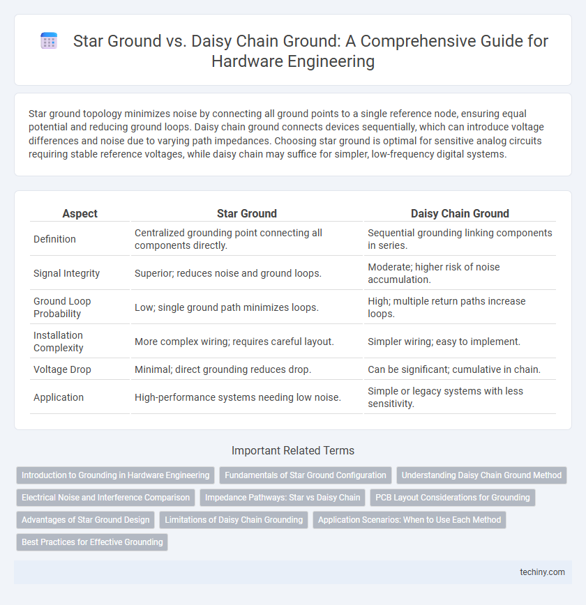
| Aspect | Star Ground | Daisy Chain Ground |
|---|---|---|
| Definition | Centralized grounding point connecting all components directly. | Sequential grounding linking components in series. |
| Signal Integrity | Superior; reduces noise and ground loops. | Moderate; higher risk of noise accumulation. |
| Ground Loop Probability | Low; single ground path minimizes loops. | High; multiple return paths increase loops. |
| Installation Complexity | More complex wiring; requires careful layout. | Simpler wiring; easy to implement. |
| Voltage Drop | Minimal; direct grounding reduces drop. | Can be significant; cumulative in chain. |
| Application | High-performance systems needing low noise. | Simple or legacy systems with less sensitivity. |
Introduction to Grounding in Hardware Engineering
Star ground and daisy chain ground are fundamental grounding techniques in hardware engineering, impacting noise reduction and signal integrity in electronic circuits. Star ground involves connecting all ground paths to a single central point, minimizing ground loop interference and ensuring a stable reference voltage. Daisy chain ground links multiple components in series to a common ground line, which is simpler but may introduce voltage differences and noise due to shared return paths.
Fundamentals of Star Ground Configuration
Star ground configuration centralizes all ground connections to a single point, minimizing ground loop interference and voltage drops in hardware engineering designs. This method ensures consistent reference potential across components, improving signal integrity and reducing noise in sensitive circuits. Proper implementation requires careful layout planning to prevent shared impedance issues common in daisy chain grounding schemes.
Understanding Daisy Chain Ground Method
The Daisy Chain Ground method connects multiple components in series, providing a reliable grounding path while minimizing ground loop interference common in complex hardware systems. This technique ensures a singular, continuous ground reference by linking ground points sequentially, which reduces noise and voltage differences across the system. Effective implementation of daisy chain grounding in hardware engineering enhances signal integrity and overall device performance compared to traditional star ground configurations.
Electrical Noise and Interference Comparison
Star ground topology minimizes electrical noise and interference by providing a single, centralized grounding point, reducing ground loop formation and voltage differentials across the system. Daisy chain grounding can introduce increased susceptibility to electromagnetic interference (EMI) and ground loop noise due to the serial connection of grounds, causing ground potential differences and current flow through the ground path. Effective hardware engineering often favors star grounding in sensitive analog and mixed-signal circuits to enhance signal integrity and reduce noise coupling.
Impedance Pathways: Star vs Daisy Chain
Star ground topology minimizes impedance by providing a single, centralized grounding point, reducing noise and ground loops in hardware circuits. Daisy chain grounding creates a sequential path with higher cumulative impedance, which can introduce voltage differences and signal interference in sensitive electronics. Optimizing impedance pathways with star grounding enhances signal integrity and electromagnetic compatibility in complex hardware designs.
PCB Layout Considerations for Grounding
Star ground layouts in PCB design minimize ground loop interference by routing all ground connections to a single, central node, enhancing signal integrity and reducing noise. Daisy chain grounding connects ground points sequentially, which can introduce unwanted impedance and potential ground loops, negatively impacting sensitive analog and high-speed digital circuits. Optimal PCB grounding requires careful evaluation of current return paths and noise coupling, often favoring star ground configurations in mixed-signal or high-frequency applications to maintain electromagnetic compatibility (EMC) standards.
Advantages of Star Ground Design
Star ground design offers superior noise reduction by creating a single reference point that prevents ground loops and minimizes voltage differences across the circuit. This method enhances signal integrity and improves overall system performance in sensitive hardware applications. It also simplifies troubleshooting by isolating ground paths, making it a preferred choice in complex electronic systems.
Limitations of Daisy Chain Grounding
Daisy chain grounding in hardware engineering faces limitations such as increased electrical noise and potential ground loop issues, which can degrade signal integrity in complex circuits. This method relies on a single path for grounding, making it vulnerable to voltage drops and grounding faults that affect the entire chain. Star grounding, by contrast, offers a more reliable approach by providing individual grounding paths, minimizing interference and ensuring stable reference potentials for sensitive components.
Application Scenarios: When to Use Each Method
Star ground configurations excel in complex electronic systems where minimizing noise and avoiding ground loops are critical, such as in precision measurement instruments and audio equipment. Daisy chain grounds are suitable for simpler, linear circuit layouts like signal processing chains or LED arrays, where ease of implementation and reduced wiring complexity are prioritized. Selecting the appropriate grounding method depends on system sensitivity, grounding point accessibility, and the need to balance noise reduction with design simplicity.
Best Practices for Effective Grounding
Star ground topology offers minimized ground loop interference by connecting all ground points to a single reference node, ensuring stable voltage levels across components. Daisy chain grounding risks increased noise and voltage drops due to sequential grounding paths, which can degrade signal integrity in sensitive hardware systems. Best practices emphasize using star grounding in complex circuits to improve EMI performance and reduce ground potential differences, enhancing overall hardware reliability.
Star Ground vs Daisy Chain Ground Infographic