Cutoff frequency defines the point where a hardware system's response drops significantly, marking the boundary between passband and stopband in filters or amplifiers. Resonant frequency represents the natural oscillation frequency at which a system stores and transfers energy most efficiently, often causing peak amplitude in circuits like LC tanks or mechanical structures. Understanding the distinction between cutoff and resonant frequencies is crucial for designing stable hardware with optimal signal filtering and energy transfer characteristics.
Table of Comparison
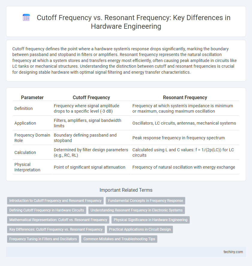
| Parameter | Cutoff Frequency | Resonant Frequency |
|---|---|---|
| Definition | Frequency where signal amplitude drops to a specific level (-3 dB) | Frequency at which system's impedance is minimum or maximum, causing maximum oscillation |
| Application | Filters, amplifiers, signal bandwidth limits | Oscillators, LC circuits, antennas, mechanical systems |
| Frequency Domain Role | Boundary defining passband and stopband | Peak response frequency in frequency spectrum |
| Calculation | Determined by filter design parameters (e.g., RC, RL) | Calculated using L and C values: f = 1/(2p(LC)) for LC circuits |
| Physical Interpretation | Point of significant signal attenuation | Frequency of natural oscillation with energy exchange |
Introduction to Cutoff Frequency and Resonant Frequency
Cutoff frequency defines the boundary in a hardware component where signal attenuation begins, typically marking the point at which power drops to half its passband value, crucial in filter and amplifier design. Resonant frequency refers to the specific frequency at which a system naturally oscillates with maximum amplitude, determined by the physical parameters of inductance, capacitance, and resistance in circuits. Understanding the distinction aids in optimizing hardware performance, as cutoff frequency controls bandwidth while resonant frequency impacts signal amplification and energy transfer efficiency.
Fundamental Concepts in Frequency Response
Cutoff frequency marks the point where a system's output power drops to half its maximum value, defining the bandwidth of filters or circuits. Resonant frequency is the specific frequency at which a system naturally oscillates with maximum amplitude due to impedance matching. Understanding the difference between these frequencies is crucial for designing frequency response characteristics in hardware engineering, ensuring optimal signal filtration and system stability.
Defining Cutoff Frequency in Hardware Circuits
Cutoff frequency in hardware circuits refers to the specific point where the output signal power drops to half of its maximum value, typically corresponding to a -3 dB level in the frequency response. This parameter defines the boundary between the passband and the stopband in filters, amplifiers, and other frequency-dependent components. Unlike resonant frequency, which is where a system naturally oscillates with maximum amplitude, the cutoff frequency marks the limit beyond which signals are significantly attenuated.
Understanding Resonant Frequency in Electronic Systems
Resonant frequency in electronic systems is the specific frequency at which an electrical circuit naturally oscillates with maximum amplitude due to inductive and capacitive reactances canceling each other out. Unlike cutoff frequency, which defines the boundary where signal attenuation begins, resonant frequency maximizes energy transfer and signal amplification in circuits such as LC oscillators and filters. Accurate determination of resonant frequency is crucial for designing efficient tuners, oscillators, and signal processing components with optimal frequency response.
Mathematical Representation: Cutoff vs. Resonant Frequency
Cutoff frequency is mathematically defined as the point where the output signal power drops to half its passband value, represented by \( f_c = \frac{1}{2\pi RC} \) in simple RC circuits, indicating the -3 dB bandwidth limit. Resonant frequency, \( f_r = \frac{1}{2\pi \sqrt{LC}} \), arises from the natural oscillation in LC circuit components, where inductive and capacitive reactances cancel each other out to maximize energy transfer. The cutoff frequency determines the boundary of effective signal transmission, while the resonant frequency identifies a peak response or oscillation mode within the system.
Physical Significance in Hardware Engineering
Cutoff frequency defines the threshold at which a hardware system significantly attenuates signal power, shaping filter and amplifier behavior crucial for signal integrity. Resonant frequency represents the natural oscillation rate where energy storage maximizes in inductors or capacitors, impacting noise, signal amplification, and hardware stability. Understanding both frequencies enables engineers to optimize circuit response for performance and reliability in RF, filter design, and signal processing applications.
Key Differences: Cutoff Frequency vs. Resonant Frequency
Cutoff frequency defines the point where a system's output signal power decreases to half its maximum value, marking the transition between passband and stopband in filters or circuits. Resonant frequency is the specific frequency at which a system naturally oscillates with maximum amplitude due to reactive component energy exchange, typically observed in LC circuits or mechanical systems. The key difference lies in cutoff frequency indicating a boundary for signal attenuation, while resonant frequency represents a peak response where energy storage and release are at equilibrium.
Practical Applications in Circuit Design
Cutoff frequency defines the boundary at which a circuit transitions between signal attenuation and pass-through, critical for designing filters that selectively block unwanted frequencies. Resonant frequency determines the point where reactive components store and exchange maximum energy, essential for tuning circuits such as oscillators and radio receivers. Practical circuit designs leverage cutoff frequency for bandwidth control while using resonant frequency to enhance signal amplification and selectivity.
Frequency Tuning in Filters and Oscillators
Cutoff frequency defines the boundary at which a filter significantly attenuates signal components, while resonant frequency represents the peak energy storage point in oscillators and resonant circuits. Frequency tuning in filters involves adjusting the cutoff frequency to selectively control the passband, enhancing signal clarity and system performance. In oscillators, tuning the resonant frequency stabilizes output frequency, ensuring consistent oscillations critical for timing and signal generation applications.
Common Mistakes and Troubleshooting Tips
Confusing cutoff frequency with resonant frequency often leads to design errors in filter and oscillator circuits, as cutoff frequency defines the -3dB bandwidth point while resonant frequency corresponds to peak energy storage in reactive components. A common mistake is misinterpreting the roll-off behavior near cutoff, which can distort signal attenuation expectations and stability margins. Troubleshooting involves verifying frequency response through network analyzers, checking component tolerances affecting resonance, and ensuring the measurement setup distinguishes between these critical frequencies accurately.
Cutoff frequency vs Resonant frequency Infographic