D-type flip-flops capture and store a single bit of data on the clock edge, making them simpler and ideal for data storage applications. JK flip-flops offer more versatility by eliminating invalid states found in SR flip-flops and can toggle outputs, enabling more complex state machine designs. Choosing between a D-type and JK flip-flop depends on the specific timing and control requirements of the hardware circuit.
Table of Comparison
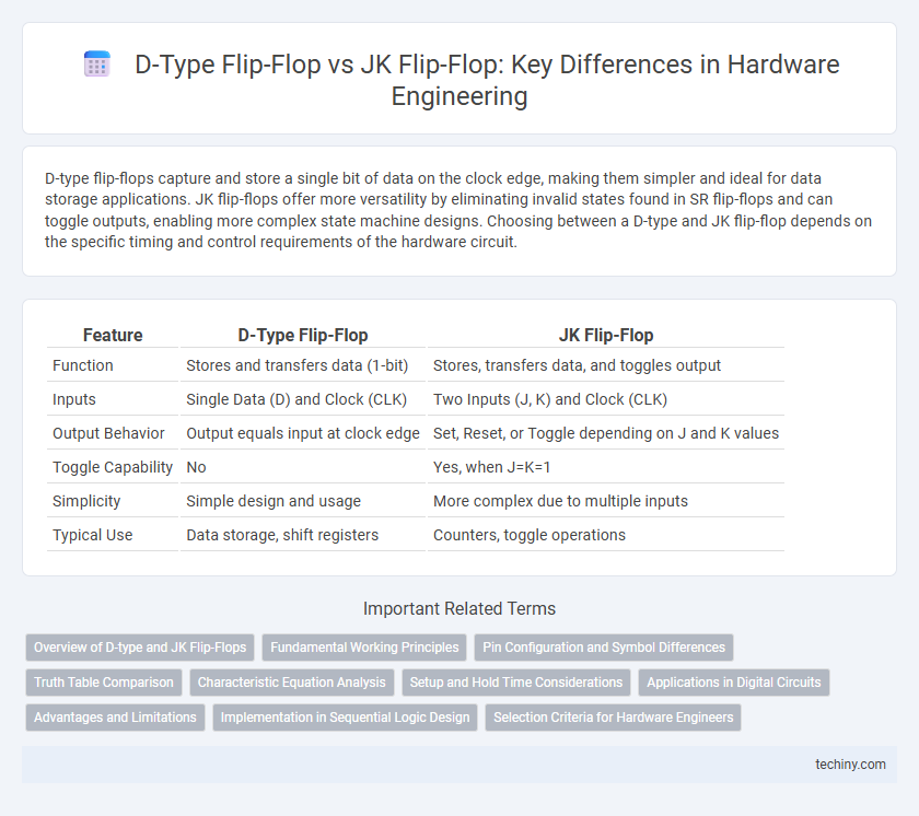
| Feature | D-Type Flip-Flop | JK Flip-Flop |
|---|---|---|
| Function | Stores and transfers data (1-bit) | Stores, transfers data, and toggles output |
| Inputs | Single Data (D) and Clock (CLK) | Two Inputs (J, K) and Clock (CLK) |
| Output Behavior | Output equals input at clock edge | Set, Reset, or Toggle depending on J and K values |
| Toggle Capability | No | Yes, when J=K=1 |
| Simplicity | Simple design and usage | More complex due to multiple inputs |
| Typical Use | Data storage, shift registers | Counters, toggle operations |
Overview of D-type and JK Flip-Flops
The D-type flip-flop captures and stores a single bit of data based on the input value at the clock pulse, providing a straightforward data latch mechanism. The JK flip-flop extends functionality with two inputs, J and K, enabling set, reset, and toggle operations depending on their combination, making it versatile for counting and state machine applications. Both flip-flops are fundamental in digital circuits, with the D flip-flop favored for data storage and the JK flip-flop preferred for complex sequential logic due to its input flexibility.
Fundamental Working Principles
The D-type flip-flop captures the input data (D) on the triggering clock edge and holds it stable until the next clock event, ensuring straightforward data storage and transfer. In contrast, the JK flip-flop operates with two inputs (J and K) that control toggling behavior, enabling clear set, reset, or toggle states based on input combinations during the clock pulse. The fundamental difference lies in the D flip-flop's single data input designed for simple latching, while the JK flip-flop's dual inputs provide versatile bistable operation critical for complex sequential logic.
Pin Configuration and Symbol Differences
The D-type flip-flop features a simple pin configuration with a single data input (D), clock input (CLK), and outputs Q and Q, enabling straightforward data storage. The JK flip-flop includes two inputs (J and K), a clock input, and outputs Q and Q, allowing toggling behavior depending on input combinations. Symbol-wise, the D flip-flop symbol shows one data input line while the JK flip-flop symbol distinctly marks the J and K inputs, illustrating the difference in control logic complexity.
Truth Table Comparison
The D-type flip-flop truth table shows a straightforward operation where the output Q takes the value of the input D on the clock edge, ensuring a single, predictable state transition. In contrast, the JK flip-flop truth table reveals more complex behavior, with outputs toggling based on the combination of inputs J and K, enabling set, reset, and toggle functions. This comparison highlights the D flip-flop's simplicity for data storage, while the JK flip-flop offers versatile control in sequential circuit design.
Characteristic Equation Analysis
The characteristic equation of a D-type flip-flop is Q(next) = D, indicating it directly transfers the input D to the output at each clock cycle, ensuring straightforward data storage and minimal logic complexity. In contrast, the JK flip-flop has the characteristic equation Q(next) = JQ' + K'Q, enabling it to perform toggling, setting, resetting, or holding states based on input combinations, which provides greater versatility in sequential circuit design. The simplicity of the D flip-flop's equation makes it ideal for delay elements and data latching, while the JK flip-flop's equation supports more complex operations such as counters and frequency division.
Setup and Hold Time Considerations
D-type flip-flops typically require shorter setup and hold times compared to JK flip-flops, making them more suitable for high-speed clock domains. JK flip-flops, due to their toggling behavior and feedback loops, often exhibit increased timing constraints that must be carefully managed during timing analysis to avoid metastability. Optimizing clock skew and ensuring precise timing margins are critical when integrating JK flip-flops in synchronous circuits.
Applications in Digital Circuits
D-type flip-flops are widely used in digital circuits for data storage, shift registers, and edge-triggered applications due to their straightforward design that latches a single input bit at the clock edge. JK flip-flops offer greater versatility, enabling toggle action and facilitating counters, frequency dividers, and complex state machines through their ability to handle input combinations without invalid states. Both flip-flops form foundational elements in synchronous sequential logic, influencing timing control and memory elements in microprocessors and digital signal processing systems.
Advantages and Limitations
D-type flip-flops offer simplicity and ease of use in storing a single bit of data, making them ideal for straightforward memory applications and register design. JK flip-flops provide greater versatility with toggle functionality, enabling more complex state machine designs but come with increased circuit complexity and potential for race conditions. While D flip-flops minimize input ambiguity and timing issues, JK flip-flops require careful clocking to avoid unstable outputs, limiting their reliability in high-speed circuits.
Implementation in Sequential Logic Design
D-type flip-flops simplify sequential logic design by providing a straightforward edge-triggered storage element that captures the input data at the clock edge, ideal for data synchronization. JK flip-flops, with their versatile toggling capability on specific input combinations, enable more complex state machines and counters by reducing the need for additional logic gates. Implementation efficiency in sequential circuits often favors D-type flip-flops for direct data storage, while JK flip-flops offer flexibility in designing toggling functions without extra combinational components.
Selection Criteria for Hardware Engineers
Hardware engineers select D-type flip-flops when simplicity and ease of data storage are prioritized, due to their single data input and straightforward design. JK flip-flops are chosen for applications requiring toggle functionality and edge-triggered control, as their two inputs provide greater flexibility in sequential logic circuits. Factors such as circuit complexity, timing requirements, and power consumption heavily influence the decision between these flip-flop types.
D-type flip-flop vs JK flip-flop Infographic